Collapsible reflective sight for a firearm
- Summary
- Abstract
- Description
- Claims
- Application Information
AI Technical Summary
Benefits of technology
Problems solved by technology
Method used
Image
Examples
first preferred embodiment
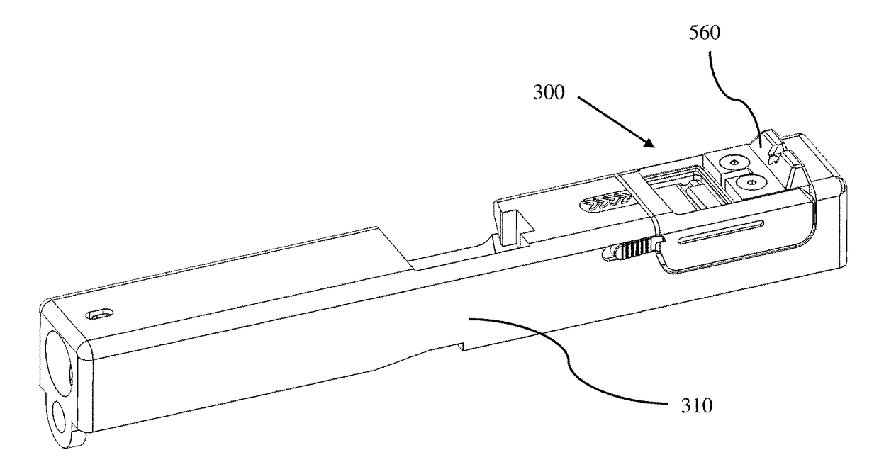
[0057]FIGS. 3A and 3B illustrate a perspective view of the collapsible optical reflective sight 300 (hereinafter may be referred to as “optical reflective sight”) mounted on a firearm slide 310, in accordance with a first exemplary preferred embodiment. FIG. 3A illustrates the collapsible optical reflective sight 300 in the deployed configuration in a usable position. Also, illustrated is an optional protective external cover 320. FIG. 3B illustrates the collapsible optical reflective sight 300 mounted on the firearm slide 310 in the collapsed configuration shown with the external cover 320 removed. The optical reflective sight 300 cannot be used in the collapsed configuration, but the mechanical sight is available for targeting, as will be discussed below.
[0058]As illustrated in FIG. 3B, in the collapsed configuration, the optical reflective sight 300 is low profile, fits within the original outline profile of the hand-gun slide 310, and includes a rear component of a mechanical or...
second preferred embodiment
[0138]FIGS. 13A and 13B illustrate a perspective view of a collapsible optical reflective sight 1300 mounted on a firearm slide 310, in accordance with a second exemplary preferred embodiment of the present invention. FIG. 13A illustrates the collapsible optical reflective sight 1300 in the deployed configuration. FIG. 13B illustrates the collapsible optical reflective sight 1300 mounted on the firearm slide 310 in the collapsed configuration. Reflective targeting of the light source dot of the second preferred embodiment operates the same as that of the first preferred embodiment.
[0139]A discussion of details similar to the first preferred embodiment will be omitted for brevity. Discussion below is directed to the overall configuration and differences from the first preferred embodiment.
[0140]As illustrated in FIG. 13B, in the collapsed configuration, like the first preferred embodiment, the collapsible optical reflective sight 1300 is low profile, fits within the original outline ...
third preferred embodiment
[0150]FIGS. 15-18 illustrate a collapsible optical reflective sight 1500 mounted on a firearm slide 310, in accordance with a third exemplary preferred embodiment of the present invention.
[0151]A discussion of details similar to the first and second preferred embodiments will be omitted for brevity. Discussion below is directed to the overall configuration and differences from the first and second preferred embodiments of the present invention.
[0152]As illustrated in FIG. 15, the collapsible reflective sight 1500 of the third preferred embodiment includes a modular base 1510, a lens 1520, a hood 1530, a battery holder 450, and a locking switch 440. As configured, the third preferred embodiment can optionally benefit from protection by an external cover (not shown) and / or an internal cover (not shown), as described above.
[0153]In the third preferred embodiment, the relative movement of the lens 1520 during deployment and collapsing with respect to the modular base 1510 and hood 1530 ...
PUM
 Abstract
Description
Claims
Application Information
 - R&D
- Intellectual Property
- Life Sciences
- Materials
- Tech Scout
- Unparalleled Data Quality
- Higher Quality Content
- 60% Fewer Hallucinations
Browse by: Latest US Patents, China's latest patents, Technical Efficacy Thesaurus, Application Domain, Technology Topic, Popular Technical Reports.
© 2025 PatSnap. All rights reserved.Legal|Privacy policy|Modern Slavery Act Transparency Statement|Sitemap|About US| Contact US: help@patsnap.com


