Cell tower and method of use

a cell tower and tower technology, applied in the field of cell towers and methods of operation, can solve the problems of undesirable electronics outbuildings, limit the range of any given cellular transmitters,

Active Publication Date: 2017-07-04
IP INVESTEMENT HOLDINGS LLC
View PDF7 Cites 35 Cited by
  • Summary
  • Abstract
  • Description
  • Claims
  • Application Information

AI Technical Summary

Problems solved by technology

The high operational frequencies, limits the range of any given cellular transmitter.
Although the monopole design improves the aesthetics of the cell tower, the electronics out-building is undesirable.

Method used


Image

  • Cell tower and method of use
  • Cell tower and method of use
  • Cell tower and method of use

Examples


Embodiment Construction

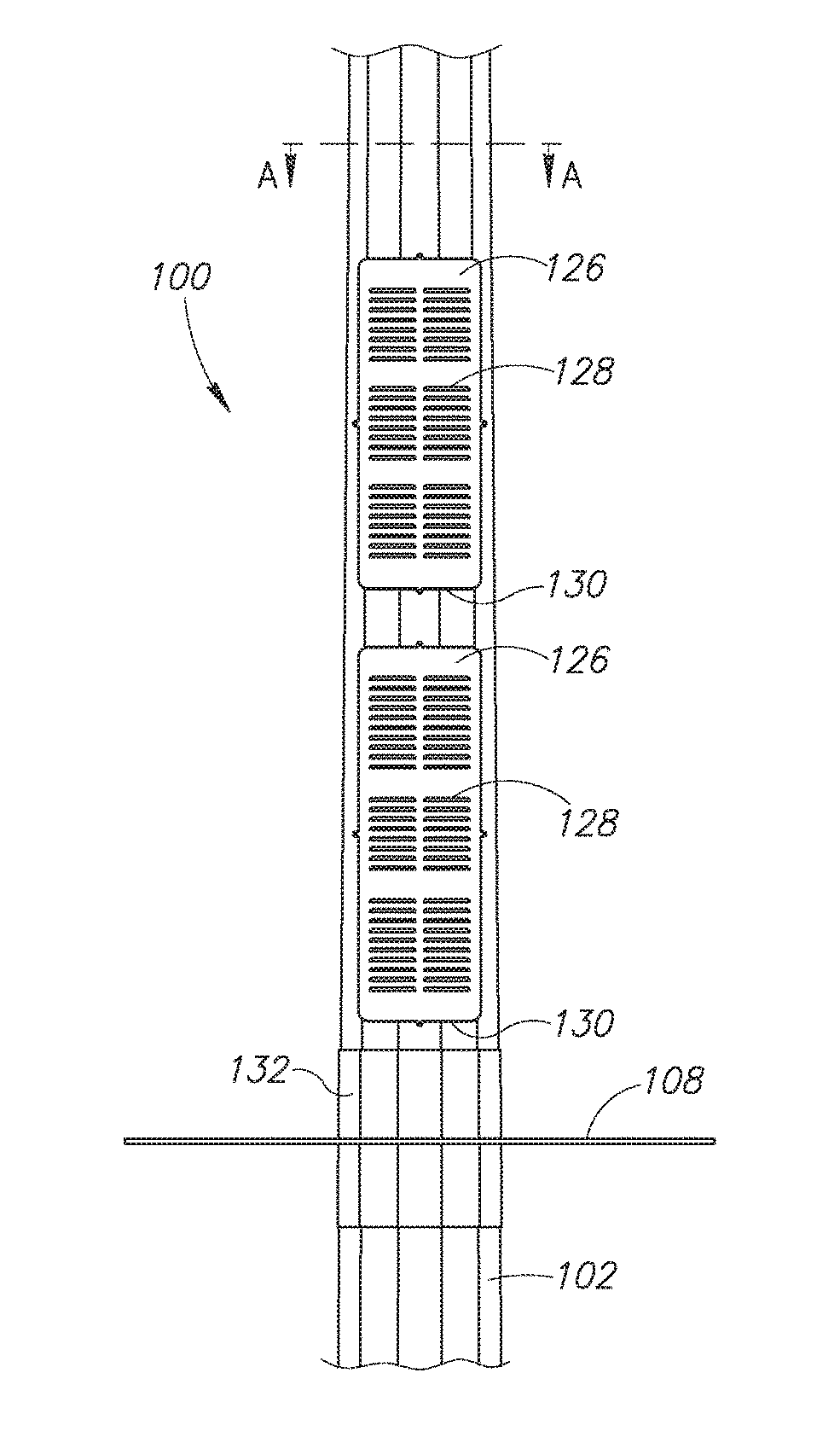
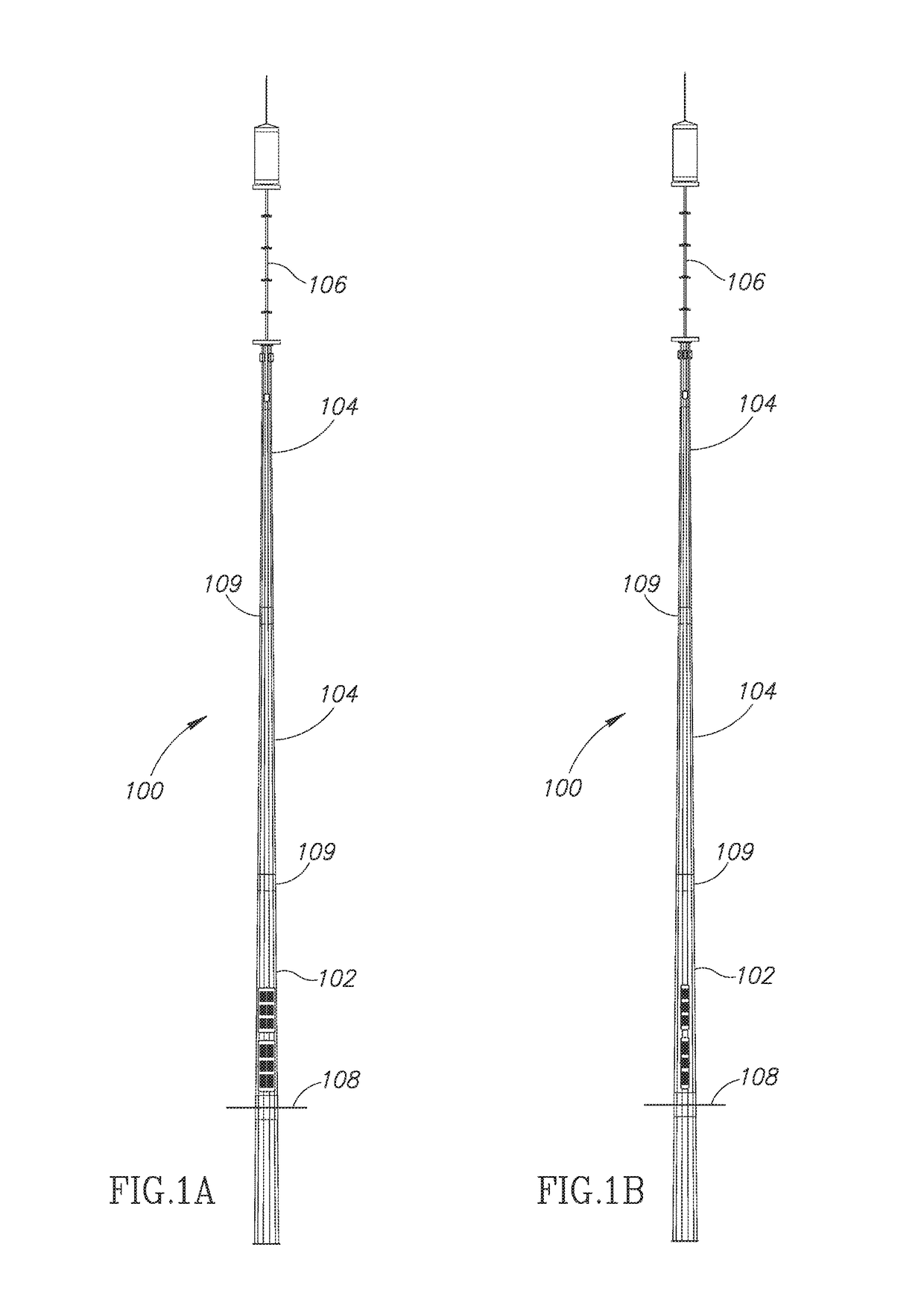
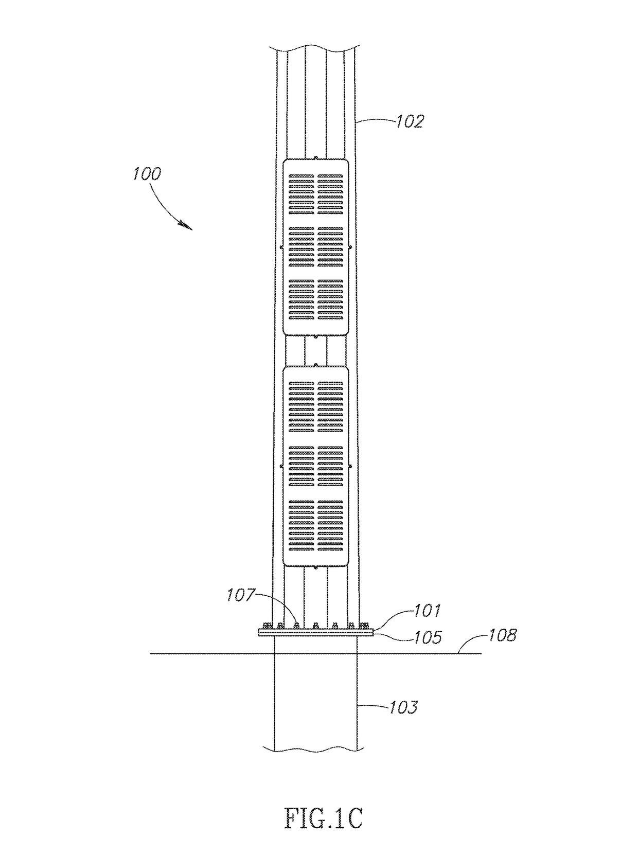
[0022]The present disclosure is directed to a cell tower design in which the electronics are integrated into the hollow center of the pole. This integration improves operational characteristics of the cell tower and also eliminates the need for an electronics out-building. The overall solution helps meet design requirements and zoning requirements for right-of-way (ROW) installation. As will be described in greater detail below, the pole also provides for modular installation of antenna sections at the top of the pole. Each antenna system is contained within a non-conductive canister that protects the antennas from the environment, provides a more environmentally and aesthetically pleasing view, and enables unimpeded wireless transmission and reception from the antennas contained within the canisters. The antenna canisters and radio placements and overall layout are conducive to allowing a multi-carrier pole with all equipment internally contained therein.

[0023]FIG. 1A illustrates a...


PUM


Abstract

A cell tower is manufactured from a steel plate that is pressed into a polygon form, such as a 12-sided polygon or a 16-sided polygon. The tower is designed for direct embedding into the ground or attachment to a buried portion. The base portion contains apertures sized to permit the installation of an equipment rack directly into the interior of the tower. Other apertures in the tower provide handholes for installation of the equipment, backup batteries, and cabling. The top section of the cell tower includes mounting members for one or more sets of cellular radio antennas and / or microwave antennas. The antennas, and associated remote radio units, are mounted to the top of the cell tower and are hidden from view by one or more shrouds. The shrouds provide a visible barrier, but have minimal impact on the radio frequency characteristics.

Description

BACKGROUND OF THE INVENTION[0001]Field of the Invention[0002]The present disclosure relates generally to cellular networks and, more particularly, to a cell phone tower and method of operation.[0003]Description of the Related Art[0004]Cellular telephone networks typically operate at high frequencies. Early cellular networks operate at 800 MHz while newer cell phone systems operate at 1900 MHz and 2400 MHz. The high operational frequencies, limits the range of any given cellular transmitter. For this reason, it is necessary for a cellular network operator to deploy an extensive network of cell towers to provide network coverage over a broad geographic area.[0005]The cell towers are sometimes mounted on tall buildings to provide extended operational range. In other areas it is necessary to build a cell tower with antennas mounted at the top portion of the tower. Early cell tower designs were often reminiscent of an oil drilling rig with a three-legged tower having cross-beams between ...

Claims


Application Information

Patent Timeline
Patent Type & Authority Patents(United States)
IPC IPC(8): H04W88/10H01Q1/42E04H12/08E04H12/02E04H12/34H01Q1/44E04H12/00
CPCH01Q1/44H04W88/10E04H12/34E04H12/02E04H2012/006E04H12/003E04H12/08E04H12/342H01Q1/1228H01Q1/1242H01Q1/42H04B1/40
Inventor JABARA, GARY B.KARMIS, CHRISTOSCALIENTO, JASONDEHART, JUSTINTRAMPETTI, MICHAEL THOMASLOFQUIST, RUSSELL J.LEVINE, JONATHAN
Owner IP INVESTEMENT HOLDINGS LLC
Why Eureka
Try Eureka