Convex contact probe for the delivery of laser energy

a contact probe and laser energy technology, applied in the field of medical devices, systems and methods, can solve the problems of long-term reduction, and achieve the effect of avoiding permanent thermal damage to the pars plicata and increasing the uveoscleral

Active Publication Date: 2017-07-11
IRIDEX CORP +2
View PDF9 Cites 4 Cited by
  • Summary
  • Abstract
  • Description
  • Claims
  • Application Information

AI Technical Summary

Benefits of technology

[0011]Embodiments of the present invention provide systems, devices, and methods for treating an eye, in particular examples, a glaucomatous eye. An amount of laser energy is delivered to the pars plana of the eye by a hand-holdable device. This device comprises a hand-holdable elongate member and a contact member disposed on an end of the elongate member. A contact surface of the contact member is placed in direct contact with the eye so that a reference edge of the contact member aligns with an external reference feature of the eye, usually the limbus, and a treatment axis defined by the elongate member may form a predetermined, non-zero angle with the optical axis of the eye. Typically, amounts of laser energy are applied to the eye in an annular pattern positioned significantly posterior to that typically used for cyclodestructive procedures, thus avoiding most or all photocoagulation of the ciliary bodies. The delivered laser energy dose is still sufficient to effect a reduction of intraocular pressure. This reduction may endure for long periods after treatment. Thus, this invention effects a long-term reduction in intraocular pressure while reducing or avoiding permanent destruction of aqueous producing structures in the eye and undesired thermal damage to adjacent tissue structures, both of which are typical of conventional laser cyclophotocoagulation procedures.
[0038]Another aspect of the invention provides a device for delivering optical energy to treat an eye, the eye having a pars plana. The device comprises a handpiece, a contact member, and a laser tip. A contact member is disposed on an end of the handpiece. The contact member comprises a target tissue reference element and a treatment site spacing reference element and defines a contact surface. The laser delivery tip is adapted to couple with an optical energy source. The laser delivery tip is positioned relative to the target tissue reference element such that when the contact surface is placed in direct contact with an outer surface of the eye with the target tissue reference element aligned with a reference feature of the eye and optical energy is delivered from the laser delivery tip, the optical energy is directed toward the pars plana at an associated treatment site. The laser delivery tip is positioned relative to the treatment site spacing reference element such that a circumferential series of treatment sites are defined when the contact surface is repeatedly placed in direct contact with an outer surface of the eye with the target tissue reference element aligned with a reference feature of the eye and the treatment site spacing reference element aligned with a feature of a prior treatment and delivering an amount of pulsed laser energy to the pars plana of the eye at an associated treatment site. Delivery of an amount of pulsed laser energy from the circumferential series of treatment sites to the pars plana that is insufficient to effect therapeutic photocoagulation can be sufficient to maintain a reduction from the pre-laser treatment intraocular pressure, for example, by increasing uveoscleral outflow.

Problems solved by technology

This reduction may endure for long periods after treatment.

Method used


Image

  • Convex contact probe for the delivery of laser energy
  • Convex contact probe for the delivery of laser energy
  • Convex contact probe for the delivery of laser energy

Examples


experiment a

[0105]An initial study using a handpiece with a contact probe similar to those described above was conducted at the National University Hospital in Singapore. In the study, treatment procedures similar to those described above were conducted on a number of glaucomatous eyes. This initial study tracks glaucomatous eyes for about 6 months, the treated eyes being treated with the aforementioned handpiece and a treatment procedure using pulsed laser energy.

[0106]Patients with advanced glaucoma refractory to maximum tolerated medical and surgical treatment and a visual acuity of worse than 6 / 60 were included in the study. Patients with recent eye surgery within 3 months of enrollment, active ocular inflammation or inability to give informed consent were excluded.

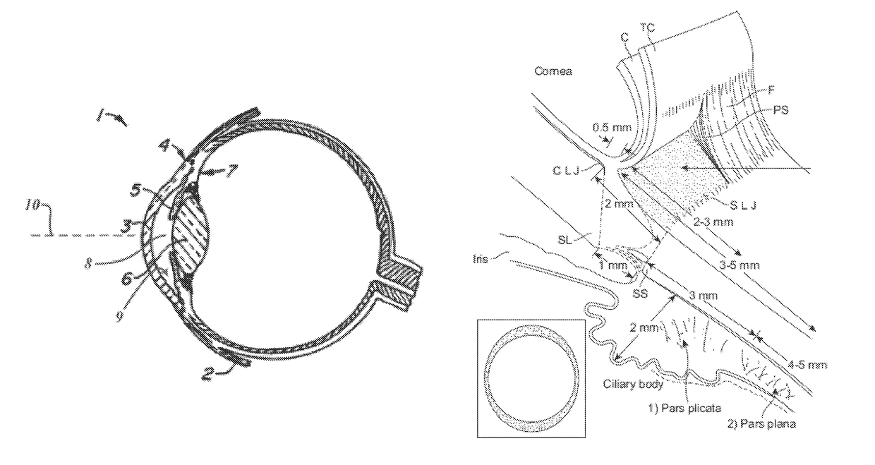
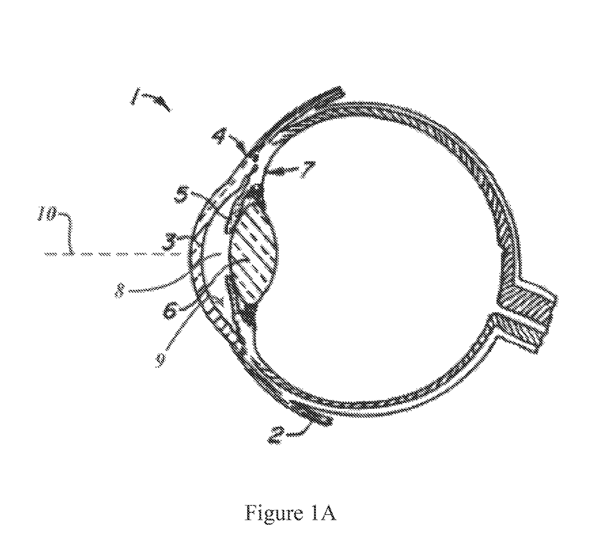
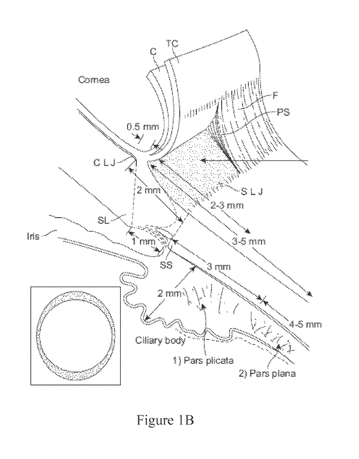
[0107]The procedure was performed by a single surgeon to patients under local anesthesia. The contact probe was designed for accurate positioning of a fiber optic at 3.0 mm behind the limbus of the eye.

[0108]The laser settings we...

experiment b

[0114]A similar study using a handpiece with a contact probe similar to those described above was conducted also at the National University Hospital in Singapore. In the study, treatment procedures using pulsed laser energy similar to those described above were conducted on a number of glaucomatous eyes. This study tracks the treated eyes for up to 18 months.

[0115]The MicroPulse™ procedure was performed by a single surgeon in the outpatient setting. Regional anesthesia with peribulbar or retrobulbar injection of 2% lidocaine was given prior to the procedure. Scleral transillumination was used to identify the position of the ciliary body as well as any areas of thinning. A diode laser emitting ball-lens tip contact probe, which is similar to those described above, was applied axially at the limbus. This probe housed a quartz fiberoptic of 600 μm in diameter. Its end protrudes 0.7 mm from the handpiece. The probe was specifically designed to allow positioning of the fiberoptic at 3.0 ...


PUM


Abstract

Systems, devices, and methods for treating a glaucomatous eye are provided. Embodiments may provide a treatment probe for treating an eye of a patient. The treatment probe may have an elongate body with a contact surface at a distal end of the elongate body. A treatment fiber or light source may be housed in the treatment probe and may be configured to direct treatment energy from the contact surface. The contact surface may be configured to couple to a surface of the eye to deliver the energy into the target area. In many embodiments the contact surface may have a convex configuration with a rounded outer shape and edge that facilitates the sweeping of the probe surface across the eye during treatment delivery. In some embodiments the probe may be swept in arc motions while delivering treatment energy to the eye.

Description

CROSS-REFERENCE TO RELATED APPLICATIONS[0001]This application claims priority to and the benefit of U.S. Provisional Patent Application No. 62 / 018,345 filed on Jun. 27, 2014, the contents of which are incorporated herein by reference in their entirety for all purposes.BACKGROUND OF THE INVENTIONField of the Invention[0002]The present invention is directed generally to medical devices, systems, and methods, particularly for treatment of an eye. In particular, embodiments of the present invention are directed toward contact probes for the delivery of laser energy, and more particularly to contact probes that are used for lowering the intraocular pressure (IOP) in human eyes afflicted with glaucoma.[0003]Glaucoma is a leading cause of blindness. Glaucoma involves the loss of retinal ganglion cells in a characteristic pattern of optic neuropathy. Untreated glaucoma can lead to permanent damage of the optic nerve and resultant visual field loss, which can progress to blindness. The loss ...

Claims


Application Information

Patent Timeline
Patent Type & Authority Patents(United States)
IPC IPC(8): A61F9/008A61F9/007
CPCA61F9/008A61F9/00781A61F2009/00865A61F2009/00868A61F2009/00891A61F9/00821A61F9/009
Inventor BUZAWA, DAVIDCHEW, PAUL T. K.
Owner IRIDEX CORP
Why Eureka
Try Eureka