High altitude gravity energy storage

a gravity energy storage and high-altitude technology, applied in the field of gravity energy storage, can solve the problems of limiting the scale and/or location of the energy storage solution, central cost, and no energy storage solution that is clos

Active Publication Date: 2017-07-11
STRATOSOLAR INC
View PDF12 Cites 3 Cited by
  • Summary
  • Abstract
  • Description
  • Claims
  • Application Information

AI Technical Summary

Problems solved by technology

As with all energy storage solutions the central problem is cost.
There is as yet no energy storage solution that is close to achieving this goal.
Most of the various forms of existing and proposed gravity energy storage also suffer from geographic constraints that limit their scale and / or location.
They are fragile, carry small payloads and are used for one flight.
This means of construction combined with the limited strength of available membrane materials has limited the scale of blimps to a volume of a few thousand cubic meters.
Aerostats lack propulsion systems, but have tethers that are at least as heavy.
In both cases it has proven impractical to provide sufficient buoyancy or a sufficiently light blimp to enable operation in the low stratosphere.
The engineering and operational constraints of doing this combined with the lack of an economic or military demand have meant that this option has never been explored.
There is no moisture or clouds in the stratosphere and turbulent weather patterns like thunderstorms and hurricanes do not reach high enough to have effect at an altitude of 20 km.
There have been attempts at building long endurance high altitude airships to fly at 20 km altitude and above, but none have as yet succeeded due to the difficult engineering challenges of limited buoyancy posed by the thin atmosphere.
No prior art airship or aerostat has been designed to stay aloft on a permanent basis.
They both have limited endurance and both must avoid bad weather.
There have been proposals for long endurance high altitude aircraft or airships to “station keep” and act as communications and observation hubs, but the operating constraints have proven too difficult.
Providing sufficient energy to station keep in the worst case winds of around 50 m / s has proven impractical.
This results in higher daily solar energy incident on a surface.
Current photovoltaic electricity systems suffer from several problems.
Their high capital costs make the cost of the energy they produce uncompetitive without subsidy.
Large-scale systems in the best sunny geographic locations also have high ancillary costs to compensate for the long transmission distance from the system to the average power user.
Current systems consequently consume large areas of land and significant quantities of construction materials like glass and steel needed to fabricate this large aperture array.
Weather in the form of clouds, dust, wind, rain, hail, frost and snow make power generation unpredictable and require that structures be strong and durable which adds significantly to their cost.
Robust mechanical support, motors, gears, electrical equipment etc are needed for each collector element, contributing significantly to overall cost.
The cost problem is compounded by the generally low overall energy conversion efficiency of current systems, which consequentially requires a larger surface area and more material to produce a given power output compared to higher conversion efficiency systems.
None of these proposals have been reduced to practice because of practical constraints that make them unrealistic.
At all altitudes in the troposphere, weather can be severe and the durability of current aerostat technology is poor.
The small scale of aerostats mean that they can at best only provide a small amount of power, and many thousands would be needed to provide power at a utility scale of hundreds of mega Watts.

Method used


Image

  • High altitude gravity energy storage
  • High altitude gravity energy storage
  • High altitude gravity energy storage

Examples


Embodiment Construction

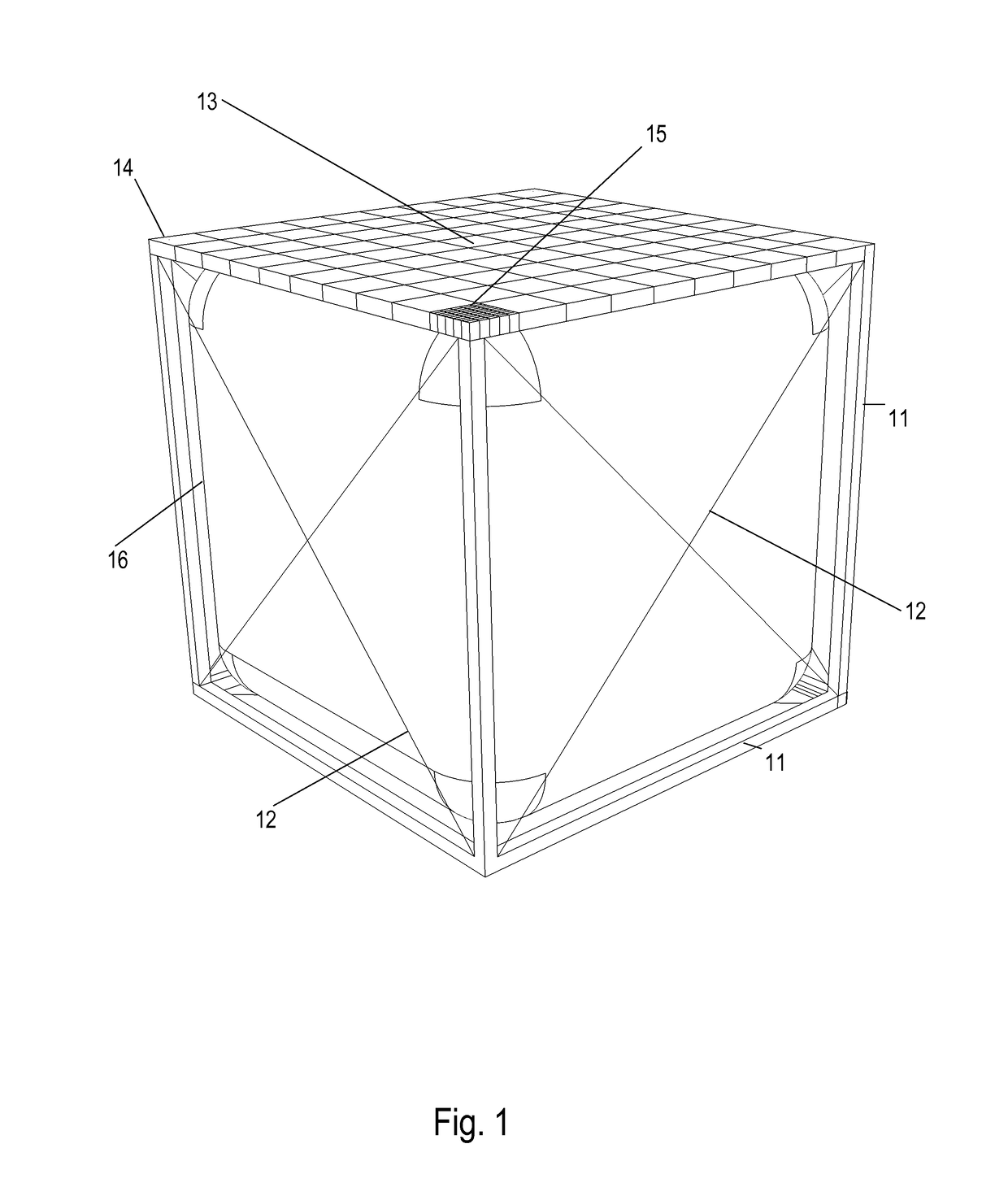
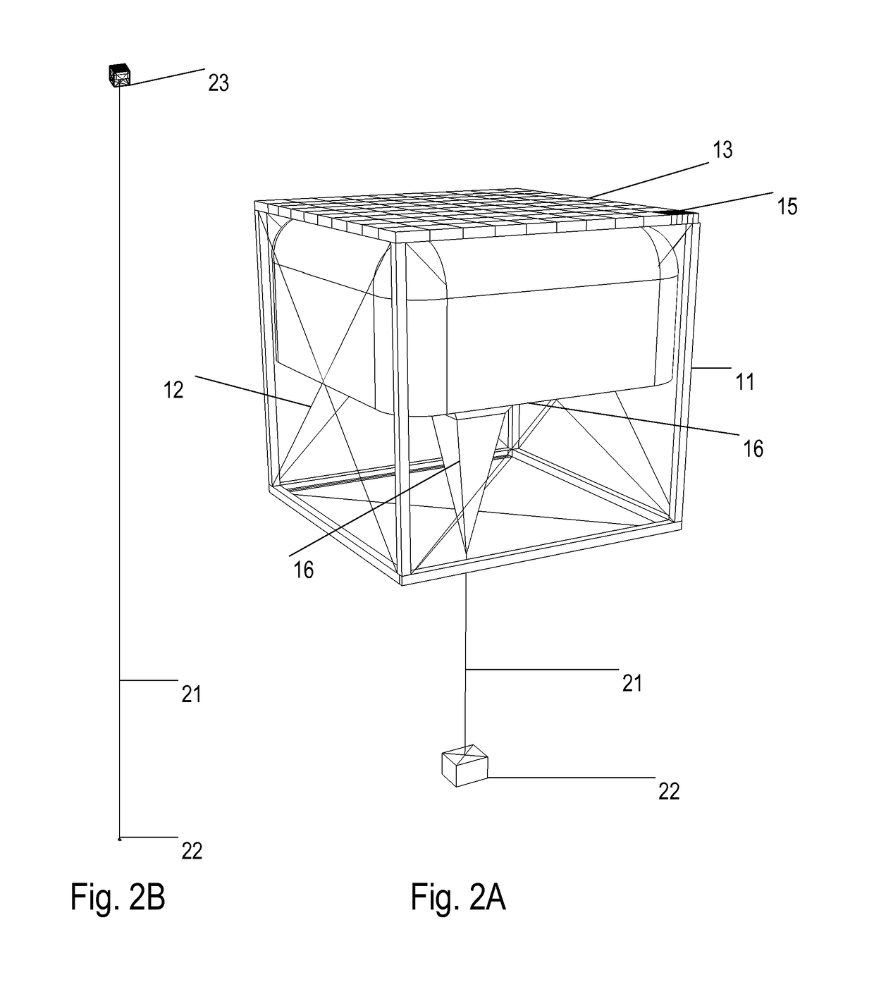
[0057]FIG. 1 shows a perspective view of a buoyant platform module 23 designed in accordance with the present invention. It consists of a rigid framework formed from struts 11, top surface 13 and cross bracing cables 12. The interior of the framework holds a gas bag 16, which contains the buoyancy gas, commonly hydrogen or helium. The top surface 13 is assembled from smaller structural sections 14. The top surface of each structural section 14 can support an array of photovoltaic panels 15 that can either partially or completely cover the top surface 13. The photovoltaic panels 15 are connected electrically with wires, DC-DC voltage converters, combiners and electricity distribution hardware to provide high voltage (HV) power output from the platform. This HV output can be AC or DC. In this embodiment when fully assembled, the overall structure is a rigid cross braced cube. The length of the cube is in the region of 100 meters. The dimensions are set by the buoyancy available at the...


PUM


Abstract

The present invention is realized by apparatus and methods for harvesting, storing, and generating energy by permanently placing a large rigid buoyant platform high in the earth's atmosphere, above clouds, moisture, dust, and wind. Long, strong and light tethers can connect the buoyant structure to the ground which can hold it in position against wind forces. Weights suspended from the buoyant platform with cables are raised and lowered by electric winches to store and release gravitational potential energy. High voltage transmission lines electrically connect the platform to the earth's surface. Electrical energy from the high voltage transmission lines or from photovoltaic arrays on the platform can be stored as gravitational potential energy and subsequently released as electricity from generators driven from the stored gravitational potential energy and used on the platform or transmitted via the high voltage transmission lines.

Description

CROSS-REFERENCE TO RELATED APPLICATIONS[0001]Non-provisional application Ser. No. 13 / 781,549, filed on Feb. 28, 2013. Non-provisional application Ser. No. 13 / 831,004, filed on Mar. 14, 2013.FEDERALLY SPONSORED RESEARCH[0002]Not ApplicableSEQUENCE LISTING OR PROGRAM[0003]Not ApplicableBACKGROUND[0004]Field[0005]This invention generally relates to energy storage and more particularly gravity energy storage.[0006]Prior Art[0007]An area of prior art is gravity energy storage. This uses mechanical energy to raise a mass through a height, storing energy as gravitational potential energy. Energy is subsequently retrieved by lowering the mass. The most common form is pumped storage hydroelectricity which uses an electric motor to drive a pump and transport a mass of water from a low altitude reservoir up a hill to a high altitude reservoir in order to store energy. Electrical energy is subsequently recovered as water flows back down the hill driving a turbine that drives a generator.[0008]O...

Claims


Application Information

Patent Timeline
Patent Type & Authority Patents(United States)
IPC IPC(8): F02B63/04H02S10/00B64B1/50H02S30/20H02S10/20B64B1/08
CPCB64B1/50H02S10/00H02S10/20H02S30/20B64B1/08Y02E10/50Y02E70/30
Inventor KELLY, EDMUND JOSEPHARNOLD, ROGER
Owner STRATOSOLAR INC
Why Eureka
Try Eureka