
Rear spoiler device for a vehicle

Active Publication Date: 2017-07-18
ZF CV SYST EURO BV
View PDF12 Cites 6 Cited by
  • Summary
  • Abstract
  • Description
  • Claims
  • Application Information

AI Technical Summary

Benefits of technology

The present invention aims to provide a rear spoiler device that is straightforward in structure and can easily adjust its position between the travel position and the initial position.

Problems solved by technology

Such systems are, however, generally very complex.
Furthermore, some rear spoiler systems only enable the use of relatively short air direction elements, whereby the improvement of the aerodynamics is limited.
Furthermore, the structural space in the hinge region of the rear door when the rear door is pivoted upward is very tight so that more complex rear spoiler configurations may impair the upward pivoting operation through 270°.

Method used


Image

  • Rear spoiler device for a vehicle
  • Rear spoiler device for a vehicle
  • Rear spoiler device for a vehicle

Examples


Embodiment Construction

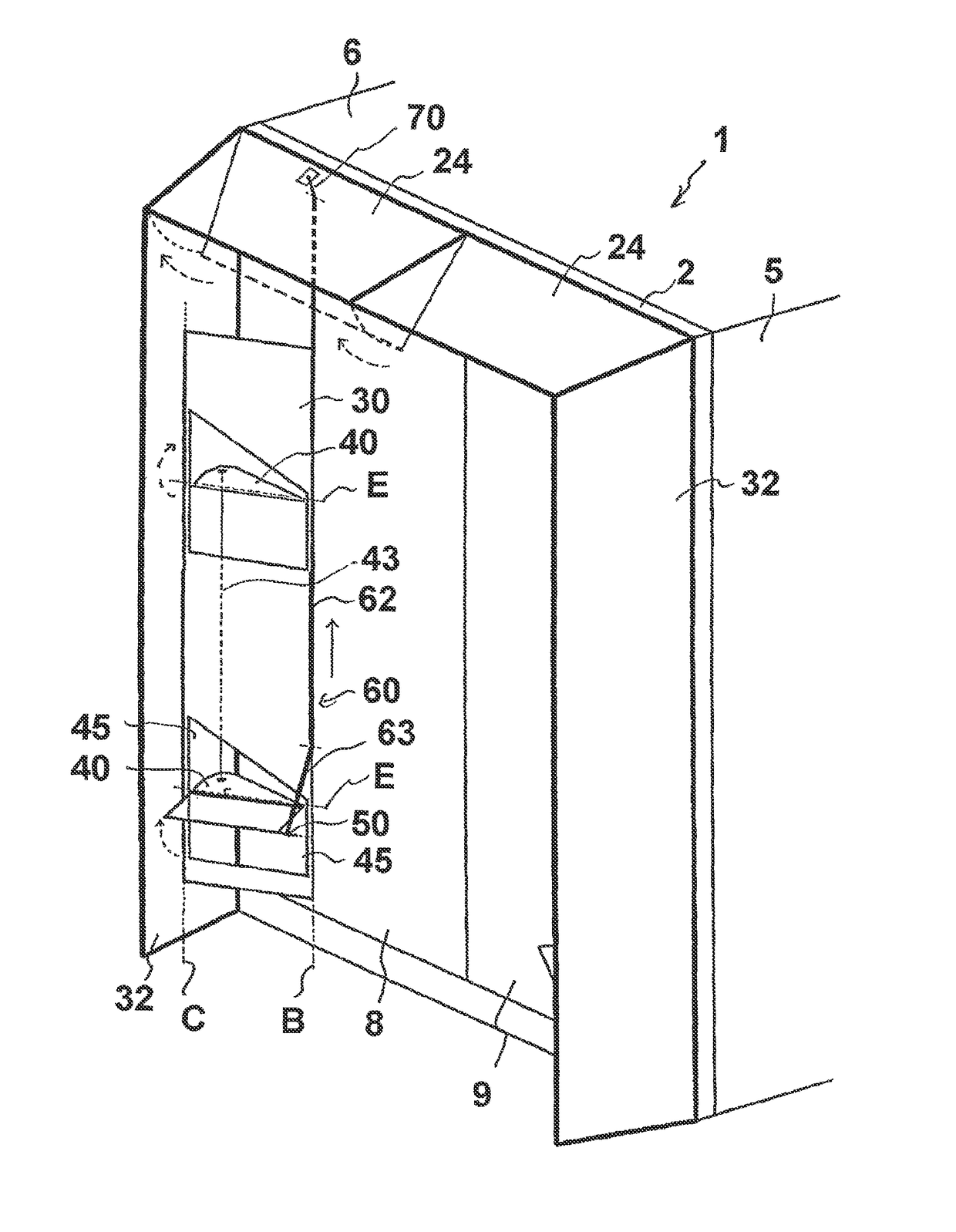
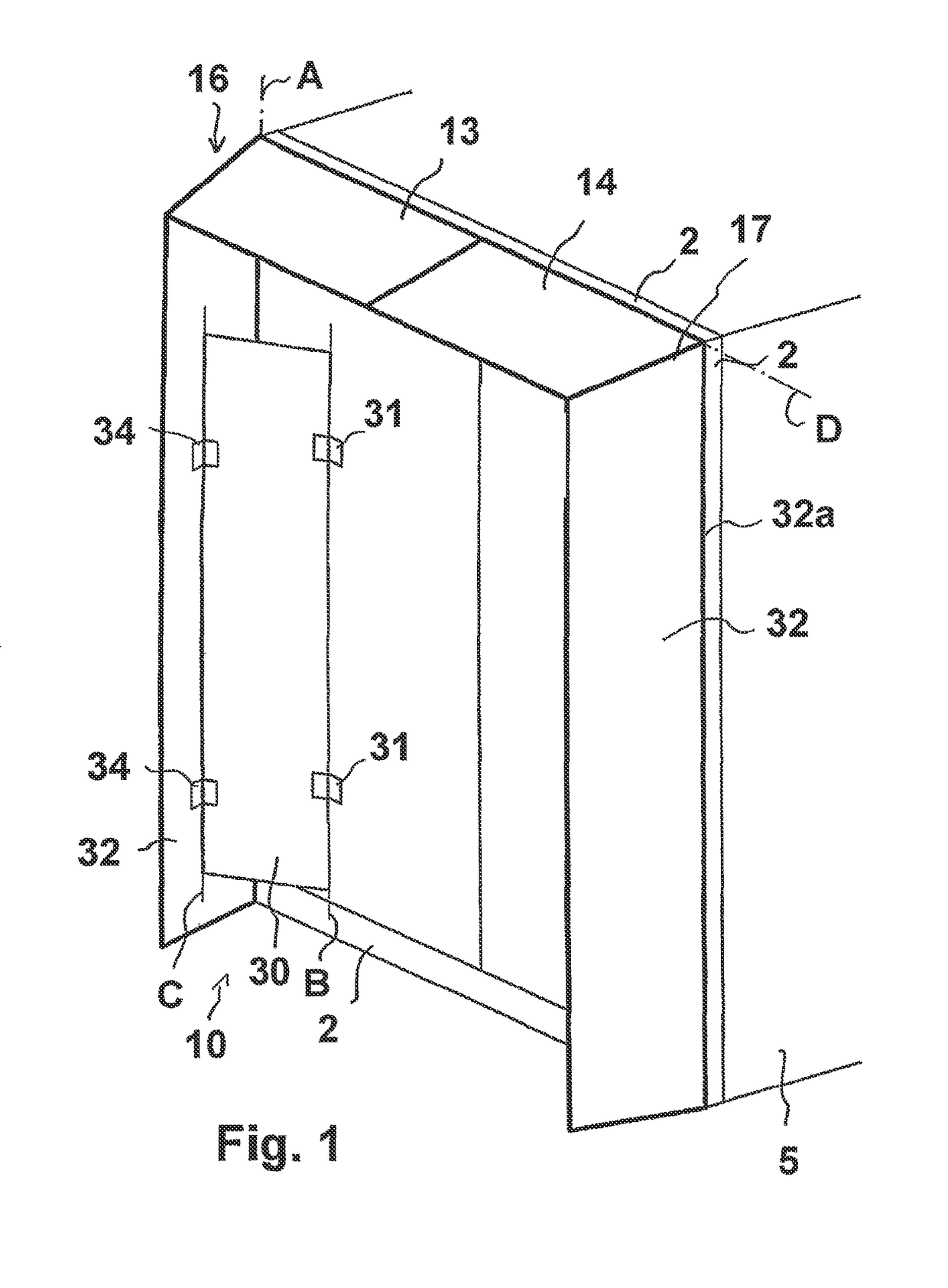
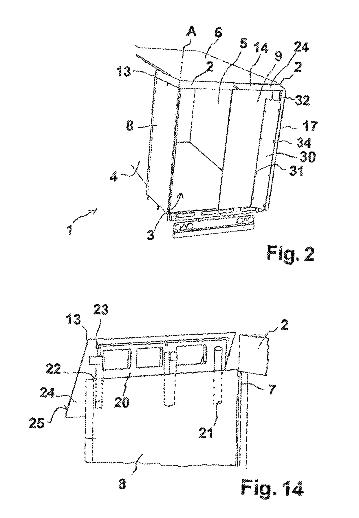
[0046]Referring to FIG. 1, a utility vehicle 1 has a vehicle structure 2, which is also referred to as a portal, in the rear region, and a storage space 3, which is delimited in an outward direction by side walls 4, 5 and in an upward direction by a vehicle roof 6. The side walls 4, 5 and the vehicle roof 6 may, for example, in a van, be constructed so as to be fixed or as load-bearing components, and accordingly be securely connected to the vehicle structure 2; furthermore, the construction of the side walls 4, 5 and optionally the vehicle roof 6 with tarpaulins is also known.

[0047]The storage space 3 can be closed at the rear by two rear doors 8, 9, which can be pivoted starting from their closed position shown in FIG. 1 about the hinge 7 thereof (or a plurality of hinges 7) through approximately 270° in an outward direction about the respective pivot axis A thereof and, for example, placed or also locked on the respective side wall 4, 5.

[0048]A rear spoiler device 10 is fitted to...


PUM


Abstract

A rear spoiler device for a vehicle with at least one rear door includes at least one lateral air-deflector element and a roof air-deflector element that can be adjusted between a default position and a travel position for contour extension and aerodynamic air conduction when the rear door is closed. The device comprises a wing, which has a first swivel joint to enable pivotable fastening to the rear door. The wing is adjustably attached to the lateral air-deflector element via at least one second swivel joint. At least one locking device is provided for locking the lateral air-deflector element with the wing. A coupling device is provided for coupling an adjustment of the locking device to the adjustment of the roof air-deflector element.

Description

FIELD OF THE INVENTION[0001]The present invention generally relates to rear spoiler devices for vehicles, e.g., utility vehicles.BACKGROUND OF THE INVENTION[0002]Rear spoilers serve to improve vehicle aerodynamics and can, accordingly, re-duce fuel consumption. They are fitted in the rear region of the vehicle and generally have air direction elements, which extend along the contours of the vehicle toward the rear, that is, with curved faces. Such rear spoilers can be secured to the roof or to the side walls.[0003]DE 20 2009 014 476 U1, DE 20 2009 014 510 U1 and DE 20 2009 015 009 U1 describe rear spoiler embodiments in which the air direction elements or spoiler elements are displaceably or pivotably arranged in order to enable unimpeded opening of the door.[0004]Pivotable or foldable rear spoilers are generally connected to the hinge of the rear door. DE 102 28 658 A1 describes different folding solutions in which planar faces, which can be pivoted by means of a hinge, are intende...

Claims


Application Information

Patent Timeline
IPC IPC(8): B62D35/00
CPCB62D35/001B62D35/007
Inventor DIECKMANN, THOMASINKERMANN, DAVIDRICHTER, TIMOZIELKE, FRANK
Owner ZF CV SYST EURO BV
Learn More