Planar loudspeaker

a loudspeaker and plane technology, applied in the field of loudspeakers, can solve the problems of destroying the driver, affecting the operation of the driver, and affecting the operation of the diaphragm, so as to achieve the effect of reducing complexity and expens

Inactive Publication Date: 2007-03-06
HARMAN BECKER AUTOMOTIVE SYST
View PDF9 Cites 1 Cited by
  • Summary
  • Abstract
  • Description
  • Claims
  • Application Information

AI Technical Summary

Benefits of technology

[0024]An advantage of the invention includes the fact that a settling protection that exhibits almost no damaging dynamic side-effects is able to be realized with relatively little complexity and expense. In addition, the implementation according to the invention generates an additional acoustic radiation in an otherwise inadequately provided bass frequency range.
[0025]Other systems, methods, features and advantages of the invention will be, or will become, apparent to one with skill in the art upon examination of the following figures and detailed description. It is intended that all such additional systems, methods, features and advantages be included within this description, be within the scope of the invention, and be protected by the following claims.

Problems solved by technology

Due to the low rigidity of the crimps, these undergo a creeping settling motion over time in response to gravity, thereby causing an eccentrically acting, irreversible misalignment of the voice coils.
The strong deflections in bridge resonance are able to overload the voice coil centering and ultimately destroy the driver.

Method used


Image

  • Planar loudspeaker
  • Planar loudspeaker
  • Planar loudspeaker

Examples


first embodiment

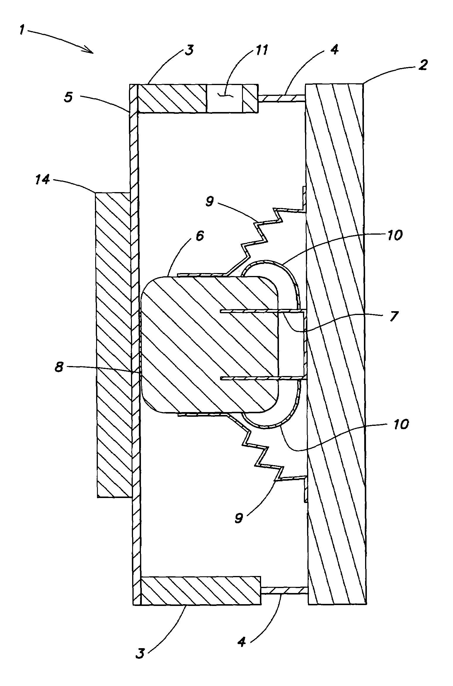
[0034]FIG. 1 illustrates a planar loudspeaker 1. The loudspeaker is configured as a asymmetrical two-panel loudspeaker, that includes a multi-resonance soundboard 2 that provides a diaphragm. The soundboard 2 has a relatively low mass, high bending stiffness, low bending-wave damping, and a self-supporting frame attachment. A rigid, usually surrounding frame 3 holds the soundboard 2 by a surrounding panel support 4, which acts as a shear-resistant articulated joint. A bridge 5 in the form, for example, of a narrow prismatic rod is connected laterally (or at the back) to the frame by a rigid connection 8 to a magnet system 6 of a driver, and simultaneously at the ends opposite the magnet. This carries the static load of the magnet system 6. A voice coil 7 passing through the annular gap of the magnet system 6 is centered by an internal crimp 10 relative to the magnet system 6 and at the same time attached to the soundboard 2. An external crimp 9 holds the static load of the magnet sy...

third embodiment

[0037]FIG. 3 is a cross sectional illustration of a planar loudspeaker 17 configured as a free, asymmetrical two-panel loudspeaker. In contrast to the embodiment of FIG. 2, in this embodiment the bridge rods 16 have been replaced by a surrounding disk spring 18. The static function of the disk spring 18 is the same as that for the rods 16 in FIG. 2—with a different resulting acoustic behavior, however. The soundboard 2 is shielded from the possible presence of a nearby wall of a building, thereby providing a helpful remedy against the undesirable “wall effect”.

[0038]FIG. 4 is a cross sectional illustration of a fourth loudspeaker embodiment configured as a asymmetrical two-panel loudspeaker 19. Notably, this embodiment is configured and arranged as a closed, asymmetrical two-panel loudspeaker. This embodiment is similar to the embodiment of FIG. 3, with the principal exception that this embodiment does not include the ventilation openings 11 of the embodiment of FIG. 3. In addition,...


PUM


Abstract

The invention relates to a planar loudspeaker comprising a light, thin soundboard (2) which may be energized to produce multiply-reflected bending waves, a surrounding frame (3) holding the soundboard (2) in an articulated, shear-resistant manner; at least one driver (6, 7, 9, 10) connected to the soundboard (2) to energize the soundboard (2); and at least one bridge (13, 16, 18, 20, 22, 25), rigidly connecting the at least one driver (6, 7, 9, 10) to the frame (3), wherein the bridge or at least one of the bridges (13, 16, 18, 20, 22, 25) is connected to the damping board (14).

Description

CLAIM OF PRIORITY.[0001]This patent application claims priority to International Application PCT / EP01 / 08104 filed on Jul. 13, 2001.FIELD OF THE INVENTION.[0002]This invention relates to the field of loudspeakers, and in particular to a planar loudspeaker comprising a light, thin soundboard that may be energized to produce multiple-reflected bending waves. A surrounding frame holds this board in an articulated manner, At least one driver is connected to and energizes the soundboard, and at least one bridge rigidly connects the at least one driver to the frame.RELATED ART[0003]U.S. Pat. No. 5,701,359 discloses a rigid-panel-type loudspeaker that functions on the principle of a free piston, wherein the sound-radiating surface (e.g., a diaphragm) is rigid (e.g., like a piston). The sound-radiating surface does not effect any significant flexural vibrations in the operating frequency range, and the rigid panel provided as the sound-radiating surface is free (i.e., open and not enclosed b...

Claims


Application Information

Patent Timeline
Patent Type & Authority Patents(United States)
IPC IPC(8): H04R25/00H04R7/04
CPCH04R7/045
Inventor BACHMANN, WOLFGANGKRUMP, GERHARDREGL, HANS-JURGENZIGANKI, ANDREAS
Owner HARMAN BECKER AUTOMOTIVE SYST
Why Eureka
Try Eureka