Optical based system and method for monitoring turbine engine blade deflection

a technology of optical based systems and turbine engines, applied in the field of turbine engines, can solve the problems of increasing the likelihood that the system will remain operational, and achieve the effect of increasing the likelihood

Inactive Publication Date: 2017-07-18
SIEMENS ENERGY INC
View PDF29 Cites 3 Cited by
  • Summary
  • Abstract
  • Description
  • Claims
  • Application Information

AI Technical Summary

Benefits of technology

[0006]Exemplary embodiments of the invention are directed to an optical image based system and method for monitoring turbine engine (such as industrial combustion or steam turbine engine) blade deflection during engine operation. An optical camera is coupled the exterior of an engine inspection port, with its optical image gathering lens components oriented so that its field of view is oriented within the engine and captures images of a rotating turbine blade, such as the blade tip. The camera's image capture or sampling rate matches blade rotation speed, so that successive temporal images of one or more blades taken at the same rotational position within the engine are directed to a blade deflection monitoring system (BDMS) controller. The controller correlates changes in a blade's captured image position within the camera field of view between successive temporal images taken at the same blade rotational position with blade deflection. The BDMS controller alarms or trips engine operation if the monitored blade deflection falls outside permissible operation parameters. By mounting the camera outside the engine, fewer monitoring system components are exposed to the hostile operating environment within the engine, increasing likelihood that the system will remain operational until the next scheduled maintenance cycle.

Problems solved by technology

By mounting the camera outside the engine, fewer monitoring system components are exposed to the hostile operating environment within the engine, increasing likelihood that the system will remain operational until the next scheduled maintenance cycle.

Method used


Image

  • Optical based system and method for monitoring turbine engine blade deflection
  • Optical based system and method for monitoring turbine engine blade deflection
  • Optical based system and method for monitoring turbine engine blade deflection

Examples


Embodiment Construction

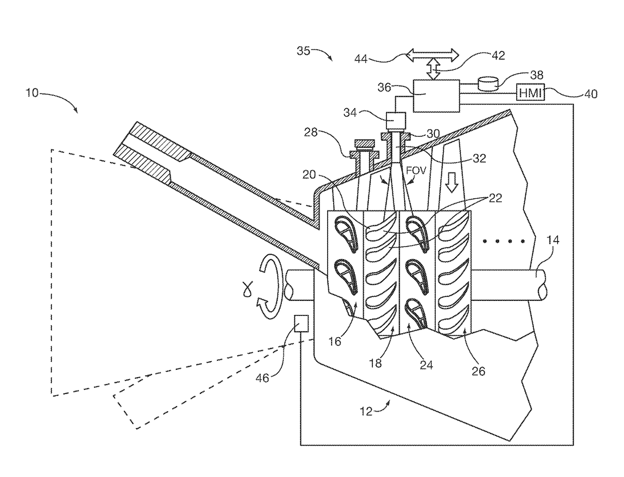
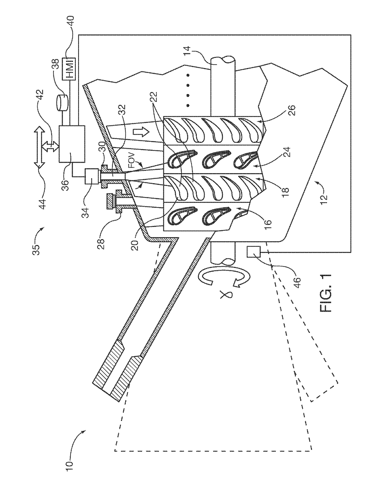
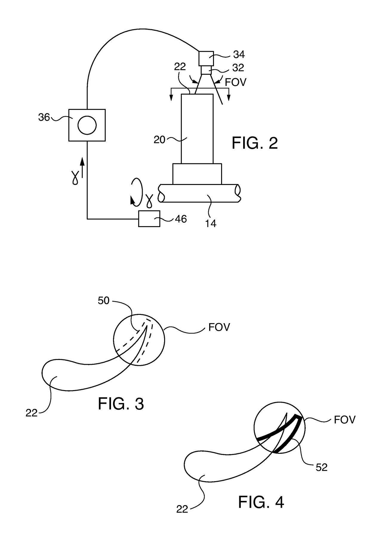
[0017]After considering the following description, those skilled in the art will realize that the teachings of the embodiments of the invention can be readily utilized in compressor or turbine blade deflection monitoring systems for steam or combustion industrial turbine engines. Image analysis of relative position of the blade within the monitoring system camera's field of view taken at one time at a blade rotation position is compared with one or more images taken at different times at the same blade rotation position during turbine engine operation. Changes of relative blade position within the same field of view orientation between successive temporal images (and / or optionally the rate of change of blade deflection between successive temporal images) are correlated with blade deflection by a blade deflection monitoring system (BDMS) controller. The controller alarms or trips the engine if monitored blade deflection falls outside permissible operation parameters.

[0018]FIG. 1 show...


PUM


Abstract

An optical based system and method for monitoring turbine engine blade deflection during engine operation. An optical camera is coupled the exterior of an engine inspection port, so that its field of view captures images of a rotating turbine blade, such as the blade tip. The camera's image capture or sampling rate matches blade rotation speed at the same rotational position, so that successive temporal images of one or more blades show relative movement of the blade tip within the image field of view. The captured successive images are directed to a blade deflection monitoring system (BDMS) controller. The controller correlates change in a blade's captured image position within the camera field of view between successive temporal images with blade deflection. The BDMS alarms or trips engine operation if the monitored blade deflection falls outside permissible operation parameters.

Description

BACKGROUND OF THE INVENTION[0001]1. Field of the Invention[0002]The invention relates to turbine engine, such as industrial gas turbine engine or steam turbine engine blade deflection monitoring systems, utilizing an optical camera to capture time-based images of blade position, such as blade tip position. Changes in blade position over time are correlated to blade deflection, which in turn is used by the monitoring system to alarm or stop turbine engine operation if the correlated parameter is out of a permissible operating parameter range.[0003]2. Description of the Prior Art[0004]Industrial turbine engines, such as steam or combustion turbine engines, utilize shaft mounted rotating turbine blades to generate mechanical work, such as for driving an electric generator in a power generation plant and / or compressing air for combustion in a combustion turbine. The compressor or turbine section blades are susceptible to deflection during turbine engine operation, for example due to inl...

Claims


Application Information

Patent Timeline
Patent Type & Authority Patents(United States)
IPC IPC(8): G01M15/14F01D21/06F01D21/00
CPCF01D21/06F01D21/003F05D2240/304F05D2270/8041
Inventor HATCHER, JR., CLIFFORDNORDLUND, RAYMOND S.
Owner SIEMENS ENERGY INC
Why Eureka
Try Eureka