Centrifuge cup

a centrifuge and cup technology, applied in the field of centrifuge cups, can solve the problem of inability to laterally move, etc., and achieve the effect of simple handling

Active Publication Date: 2017-07-25
THERMO ELECTRONICS LED GMBH
View PDF20 Cites 4 Cited by
  • Summary
  • Abstract
  • Description
  • Claims
  • Application Information

AI Technical Summary

Benefits of technology

[0005]According to one aspect of the present invention, a centrifuge cup is provided in which a permanent aerosol-tight closure is ensured during a centrifuging procedure. The opening and closing of the centrifuge cup is to be able to be performed easily, the closure automatically assuming an optimum closing position. The centrifuge cup is to be producible cost-effectively and is only to have low requirements for manufacturing tolerances. Furthermore, the closure of the centrifuge cup is to act on the centrifuge cup container with a uniformly distributed closing force.

Problems solved by technology

Lateral displacement is thus not possible even during centrifuging operation.

Method used


Image

  • Centrifuge cup
  • Centrifuge cup
  • Centrifuge cup

Examples


Embodiment Construction

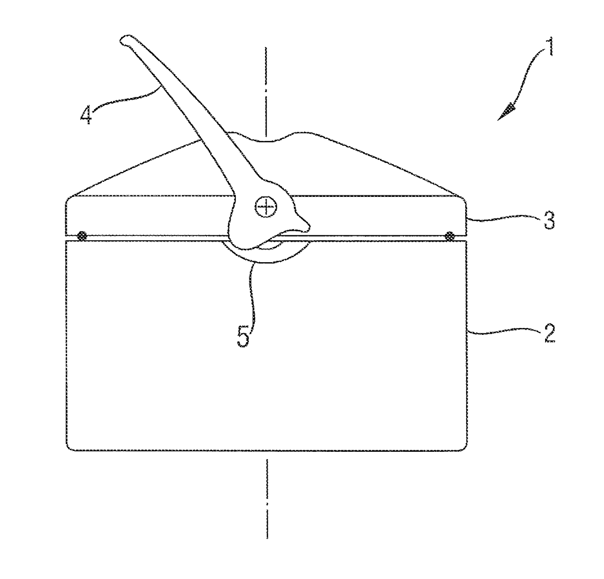
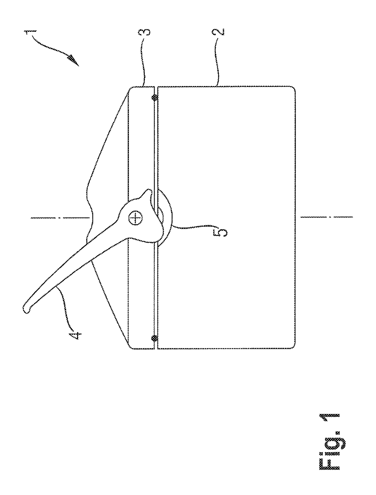
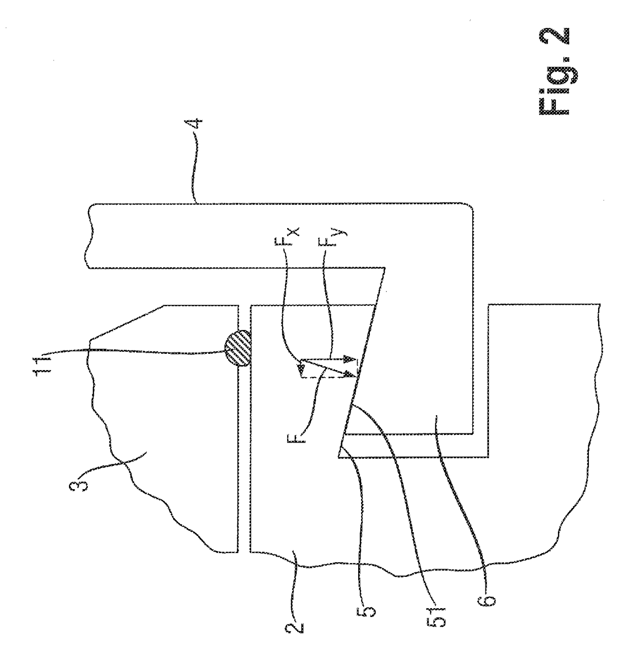
[0023]According to FIG. 1, the centrifuge cup 1 according to one embodiment of the present invention has a container 2 and a cover 3. The cover 3 has a lever 4 which is used so that the cover 3 can be closed with the container 2. It is to be noted that the first embodiment shown in FIG. 1 is a centrifuge cup implemented as round, although a centrifuge cup implemented as rectangular may also be provided with the closure explained hereafter. The lever 4 has a guide element 6 in each case on opposing sides and / or edge areas which may be introduced into a guide path 5 of the container 2 by pivoting the lever 4 (see FIG. 2).

[0024]The centrifuge cup 1 is provided with guide elements 6, which are implemented as essentially conical in cross-section. The geometry may be derived from a right circular cone (in cross-section as a so-called dovetail) or an oblique circular cone (see FIG. 2). The conical guide element 6 is shaped in such a way that an undercut is achieved with the guide path 5, w...


PUM


Abstract

The invention relates to a centrifuge cup, which has a container and a cover. The cover has a lever including a guide element in each case on opposing edge areas thereof. The guide elements are able to be introduced into an associated guide path of the container by pivoting the lever. The guide elements are implemented in such a way that in a closed state of the cover with the container, a clamping force (F) having vertical force component (Fy) and horizontal force component (Fx) is provided at a contact point or a contact line of the guide elements with the particular associated guide path.

Description

RELATED APPLICATION[0001]The present application claims the priority under 35 U.S.C. §119 of German Patent Application No. 102008031502.8, filed Jul. 3, 2008, the disclosure of which is hereby incorporated herein by reference in its entirety.FIELD OF THE INVENTION[0002]The invention relates to a centrifuge cup, which has a container and a lid having a lever, the lever having a guide element in each case on opposing edge areas and the guide elements being able to be introduced into an associated guide path of the container by pivoting the lever.BACKGROUND OF THE INVENTION[0003]Centrifuge cups are known in the prior art in which an aerosol-tight closure of a cover with an associated container is achievable. A centrifuge cup having a catch connection is described in EP 0 025 945 A1. The catch connection has projections directed in opposite directions on both the upper peripheral edge of the centrifuge cup and also on the edge of the hood, which are engaged after the application of the ...

Claims


Application Information

Patent Timeline
Patent Type & Authority Patents(United States)
IPC IPC(8): B65D45/14B65D45/20B04B5/04B65D45/04
CPCB04B5/0421B65D45/04B65D45/14B65D45/20
Inventor BALLHAUSE, NORMAN
Owner THERMO ELECTRONICS LED GMBH
Why Eureka
Try Eureka