Radar sensor including waveguide structure

Active Publication Date: 2022-01-27
ROBERT BOSCH GMBH
View PDF5 Cites 1 Cited by
  • Summary
  • Abstract
  • Description
  • Claims
  • Application Information

AI Technical Summary

Benefits of technology

[0004]An object of the present invention is to provide a radar sensor which may be produced easi

Problems solved by technology

At the same time, the use of additional fastening means is avoided by the integrally joined conne

Method used


Image

  • Radar sensor including waveguide structure
  • Radar sensor including waveguide structure
  • Radar sensor including waveguide structure

Examples


Embodiment Construction

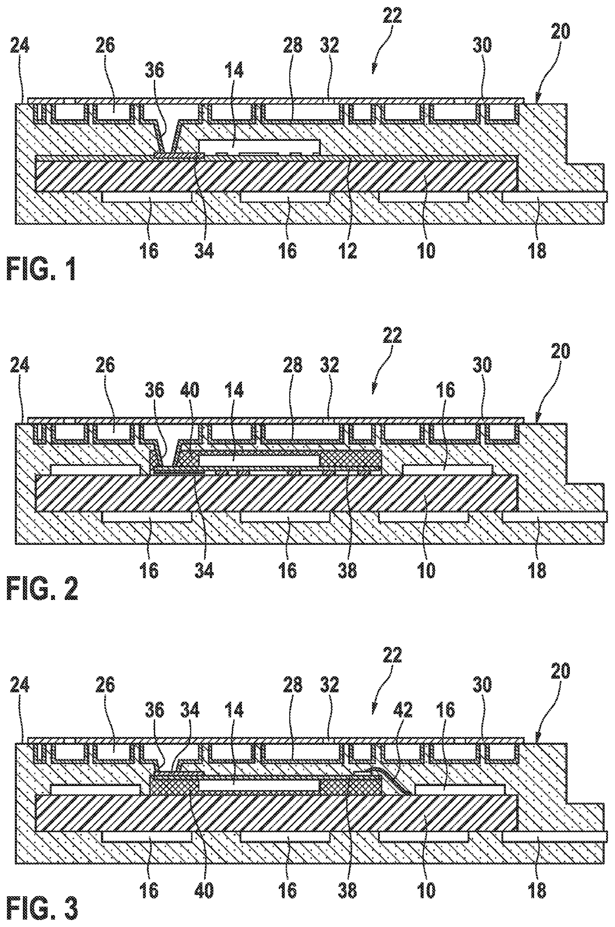
[0025]The radar sensor shown in section in FIG. 1 includes a circuit board 10, which includes a high-frequency capable carrier substrate 12 on the upper side and is equipped with a high-frequency component 14. High-frequency component 14 may be, for example, an MMIC package (monolithic microwave integrated circuit including plastic housing). On the lower side, circuit board 10 is equipped in a known way with further electronic components 16 (e.g., ICs, SMDs (surface mounted devices)) and with a contact unit 18 for a connection plug. Entire circuit board 10 including the components arranged thereon (with exception of a part of contact unit 18) is extrusion coated using a mold 20 made of an electrically nonconductive plastic, preferably using a thermosetting plastic, optionally also using a thermoplastic. A waveguide structure 22 is formed in the upper side of mold 20, which includes a number of cavities 26 open toward outer surface 24 of the mold, whose walls were made conductive by ...


PUM


Abstract

A radar sensor. The radar sensor includes a high-frequency component situated on a circuit board and a waveguide structure, which is connected via a coupling structure to the high-frequency component. The waveguide structure is formed in a mold, which is injection molded to a part of the circuit board supporting the high-frequency component.

Description

CROSS REFERENCE[0001]The present application claims the benefit under 35 U.S.C. § 119 of German Patent Application No. DE 102020209307.5 filed on Jul. 23, 2020, which is expressly incorporated herein by reference in its entirety.FIELD[0002]The present invention relates to a radar sensor including a high-frequency component situated on a circuit board and a waveguide structure, which is connected via a coupling structure to the high-frequency component.BACKGROUND INFORMATION[0003]A radar sensor of this type is described in German Patent Application No. DE 10 2014 208 389 A1, in which the waveguide structure is an array of waveguide antennas.SUMMARY[0004]An object of the present invention is to provide a radar sensor which may be produced easily and with low manufacturing tolerances and is robust with respect to environmental influences.[0005]This object may be achieved according to an example embodiment of the present invention in that the waveguide structure is formed in a mold, whi...

Claims


Application Information

Patent Timeline
IPC IPC(8): H01Q1/42H05K1/02H01P3/08G01S7/02
CPCH01Q1/42H05K1/0243H01Q13/00G01S7/027H05K2201/10151H01P3/081G01S7/03H01Q13/06H01Q1/225H01P3/121H01Q21/06H01Q23/00H01Q21/0006H01Q1/422H01Q1/405H01P5/107G01S7/028G01S7/032H01Q1/2283H01P1/203H01Q1/38
Inventor FISCHER, ALEXANDERKUGLER, ANDREASHIMMELSTOSS, ARMINGREVENT, CORINNEZANDER, ISABELMAENZ, TORSTENSILBER, CHRISTIAN
Owner ROBERT BOSCH GMBH
Why Eureka
Try Eureka