Cooling fan module

a cooling fan and module technology, applied in the direction of machines/engines, mechanical equipment, liquid fuel engines, etc., can solve the problems of reducing the comfort of passengers during vehicle operation, affecting and generating high levels of noise, so as to achieve the effect of improving the efficiency of the cooling fan module and low manufacturing cos

Active Publication Date: 2017-07-25
BROSE FAHRZEUGTEILE GMBH & CO KG
View PDF36 Cites 1 Cited by
  • Summary
  • Abstract
  • Description
  • Claims
  • Application Information

AI Technical Summary

Benefits of technology

[0010]The concept underlying the invention entails guiding the swirling reverse flow in a preferred direction and de-spinning it by means of a reverse flow guide device provided specifically for this purpose. The reverse flow guide device rectifies the reverse flow again so that this no longer swirls, and mixes said reverse flow with the flow which flows between the inner ring of the reverse flow guide device and the fan impeller outer ring. The flow in the main flow thus remains vortex-free, even after mixing with the flow mixed with the reverse flow by the reverse flow guide device such that a vortex-free flow reaches the fan blades. As a result, the noise emitted by the cooling fan module is reduced. This thus also leads to improved flow behaviour of the cooling fan module, which increases the effectiveness of the cooling fan module.
[0013]In one embodiment, the reverse flow guide device comprises a large number of air guide fins which are provided between the inner ring and the outer ring and which extend from the inner ring to the outer ring, in a radial direction for example. These air guide fins enable the swirling reverse flow to be rectified even better, thus improving the flow behaviour of the cooling fan module even more.
[0014]In a further preferred embodiment, the air guide fins and / or the transition are designed elastically such that the fan impeller can be inserted through the guide device. In this way the cooling fan module can be mounted in a very simple fashion.
[0016]In a further preferred embodiment, the frame with the air guide device having the elastic transition and / or the elastic air guide fins is designed as a single-piece two-component injection-moulded part. The costs of manufacturing the cooling fan module can be significantly reduced in this manner.
[0018]In a further preferred embodiment, the fan impeller comprises a further fan impeller outer ring which is connected to the fan impeller outer ring by a large number of outer ring air guide fins. The outer ring air guide fins are designed so as to generate a radial air flow between the fan impeller outer ring and the second fan impeller outer ring. The radial air flow may flow from the inside to the outside or from the outside to the inside depending on the orientation of the outer ring air guide fins. The efficiency of the cooling fan module can be improved even more in this manner. This preferred embodiment of the fan impeller may also be used and inserted in other devices, such as ventilators, turbines, compressors, etc, which do not have a reverse flow guide device, for example.
[0019]In a further preferred embodiment, the frame and the reverse flow guide device are designed together as a single piece. This embodiment of the cooling fan module is particularly advantageous with regard to low manufacturing costs for the cooling fan module.

Problems solved by technology

The swirling gap flow works against the main flow, leading to a negative impact on the flow behaviour of the cooling fan module.
This defective flow sometimes leads to a very high level of noise being generated, reducing the comfort of the passengers during vehicle operation.

Method used


Image

  • Cooling fan module
  • Cooling fan module
  • Cooling fan module

Examples


Embodiment Construction

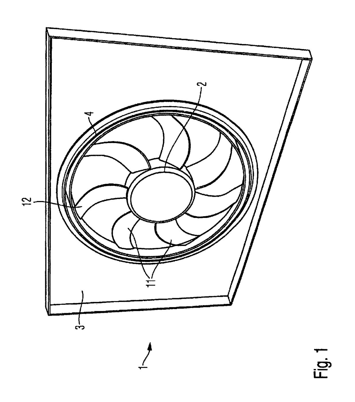
[0041]FIG. 1 shows a perspective front view of a cooling fan module 1. The view in FIG. 1 shows the side of the cooling fan module 1 from which the cooling fan module 1 takes in air.

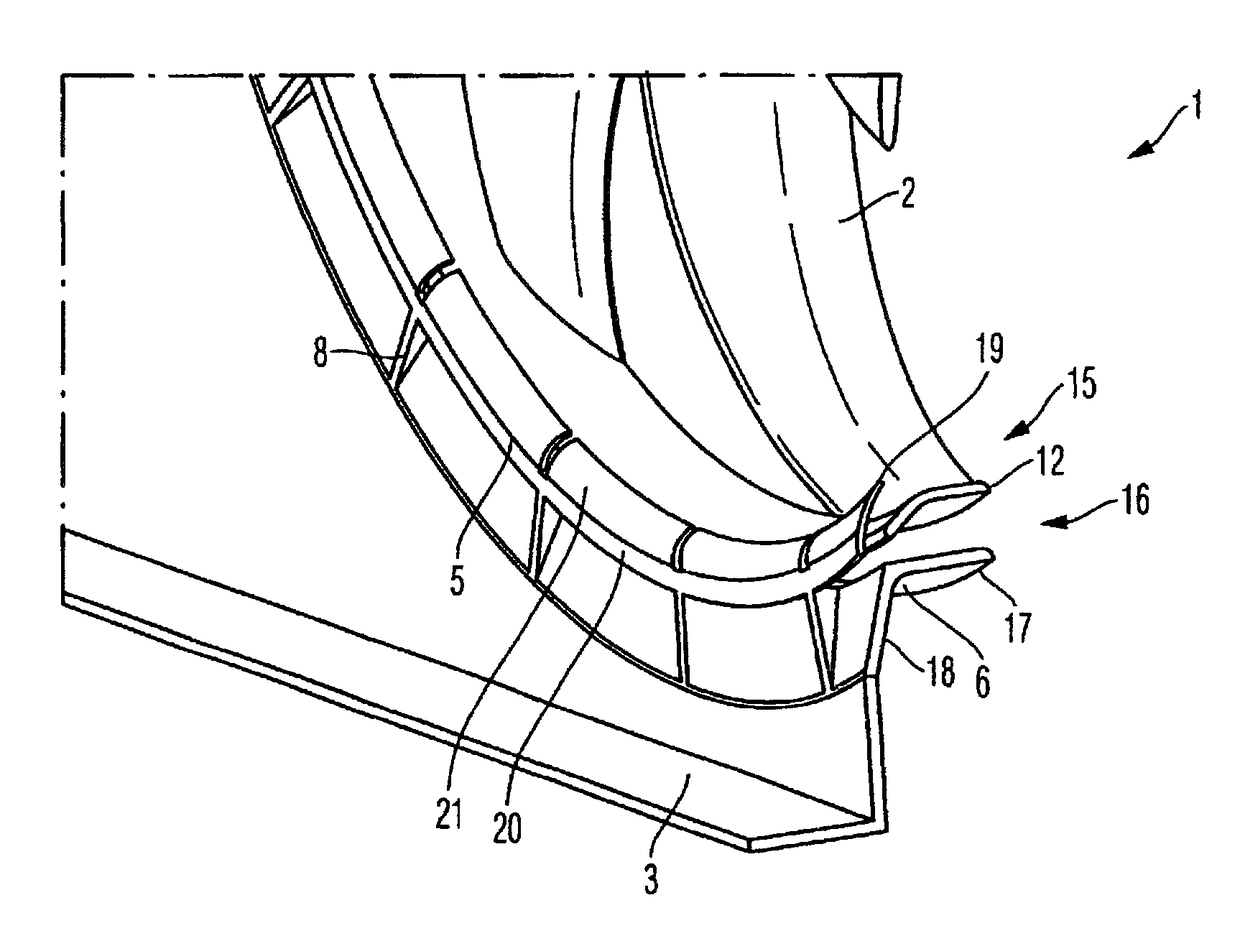
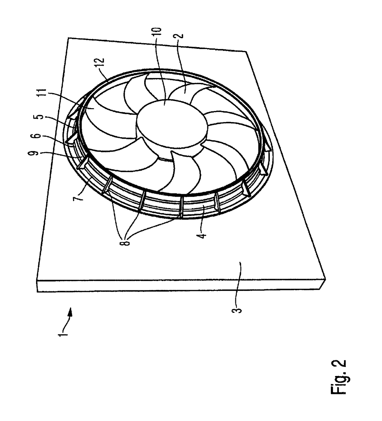
[0042]The cooling fan module 1 comprises a frame 3, which has a substantially rectangular form in this embodiment. A recess is provided within the frame 3 in which a fan impeller 2 is located. The fan impeller 2 is fixed by means of assembly struts (not illustrated) to the frame 3. A reverse flow guide device 4 is located between the fan impeller 2 and the frame 3. The reverse flow guide device 4 rectifies a reverse flow which arises as a result of the negative pressure on the intake side, such that the reverse flow no longer swirls in consequence. The reverse flow, as a rectified flow, is mixed with the main flow, which flows centrally through the fan impeller 2, once again and strikes the fan impeller blades 11 of the fan impeller 2 in rectified form.

[0043]The frame 3 is made from a plastics material, ...


PUM


Abstract

The invention relates to a cooling fan module for a motor vehicle, having a fan impeller which has a multiplicity of fan impeller blades which are connected to one another via a fan impeller outer ring, having a frame, on which the fan impeller is mounted, having an annular reverse flow guide device, which has an inner ring and an outer ring and which is designed to de-spin a reverse flow between the inner ring and the outer ring and to mix said reverse flow with the slot flow between inner ring and fan impeller outer ring.

Description

CROSS-REFERENCE TO RELATED APPLICATION[0001]This Application is a Section 371 National Stage Application of International Application No. PCT / EP2012 / 002004, filed May 10, 2012 and published as WO 2012 / 156045 A2 on Nov. 22, 2012, which is based on and claims the benefit of priority from German Patent Application No. DE 10 2011 075 801.1, filed on May 13, 2011 and German Patent Application No. DE 10 2012 207 552.6, filed on May 7, 2012, the contents of which are hereby incorporated by reference in their entirety.FIELD OF THE INVENTION[0002]The present invention relates to a cooling fan module.TECHNICAL BACKGROUND[0003]Cooling fan modules are used to cool the engine in motor vehicles. The general aim is to manufacture such cooling fan modules as economically as possible. The comfort of the vehicle occupants is also a further aspect, especially with regard to minimising the noise generated by the cooling fan module.[0004]A cooling fan module typically consists of a fan impeller, in whic...

Claims


Application Information

Patent Timeline
Patent Type & Authority Patents(United States)
IPC IPC(8): F04D29/52F04D29/16F04D29/32F01P5/06F04D29/66
CPCF04D29/526F01P5/06F04D29/164F04D29/326F04D29/663F04D29/665F04D29/666F04D29/30F04D29/32
Inventor SCHAFER, TILMANDREESEN, THOMAS
Owner BROSE FAHRZEUGTEILE GMBH & CO KG
Why Eureka
Try Eureka