Method of operating an exhaust emission control device, and corresponding exhaust emission control device

a technology of emission control device and control device, which is applied in the direction of exhaust treatment electric control, machines/engines, mechanical devices, etc., can solve the problems of ash produced during burning, ash remains in the particulate filter, and cannot be carried away from the particulate filter, etc., to achieve the effect of reliable removal of ash

Active Publication Date: 2017-08-01
AUDI AG
View PDF19 Cites 4 Cited by
  • Summary
  • Abstract
  • Description
  • Claims
  • Application Information

AI Technical Summary

Benefits of technology

[0012]According to another advantageous feature of the present invention, the model value and / or the actual value can be filtered by a bandpass filter before determining the pressure quotient. Thus, either the model value, or the actual value, or both, the model value and the actual value, may undergo filtering via a bandpass filter. The bandpass filter is capable to filter out in the frequency range of the model value and / or the actual value low and high frequencies. By filtering out the low frequencies, the signal is liberated from the mean value and thus in particular from an offset or offset error. As a result, structure tolerances and / or dynamic operating states are prevented from adversely affecting the direct formation of the pressure quotient from actual value and model value. Any impact of structure tolerances on the pressure sensors for example can be eliminated. In particular, an offset error of the pressure sensors is corrected. Moreover, the negative effect of a temperature drift of the pressure sensors on the outcome of the test to check the condition of the particulate filter can be excluded. Filtering out high frequencies reduces any interference that may be caused by signal noise for example.
[0015]According to another advantageous feature of the present invention, a model integral value is formed from the model value as a function of time and / or an actual integral value is formed from the actual value as a function of time, with the pressure quotient being a quotient of the actual integral value and the model integral value. The pressure quotient is thus not equated with the quotient of actual value and model value, but rather is equated to the quotient of the respectively integrated values, namely the actual integral value and the model integral value. The model integral value is formed through integration of the model value over time. Likewise, the actual integral value is formed through integration of the actual value over time. Any adverse effect as a result of momentary interferences can thus be minimized through integration of the model value and / or actual value.

Problems solved by technology

While the regeneration mode causes a burning of the particles, there is still the problem that ash which has been produced during burning, still remains in the particulate filter.
This ash cannot be carried away from the particulate filter during operation of the exhaust emission control device and / or during the regeneration mode.
This, however, is not reliable.

Method used


Image

  • Method of operating an exhaust emission control device, and corresponding exhaust emission control device
  • Method of operating an exhaust emission control device, and corresponding exhaust emission control device
  • Method of operating an exhaust emission control device, and corresponding exhaust emission control device

Examples


Embodiment Construction

[0032]The depicted embodiment is to be understood as illustrative of the invention and not as limiting in any way. It should also be understood that the figures may not necessarily be to scale. In certain instances, details which are not necessary for an understanding of the present invention or which render other details difficult to perceive may have been omitted.

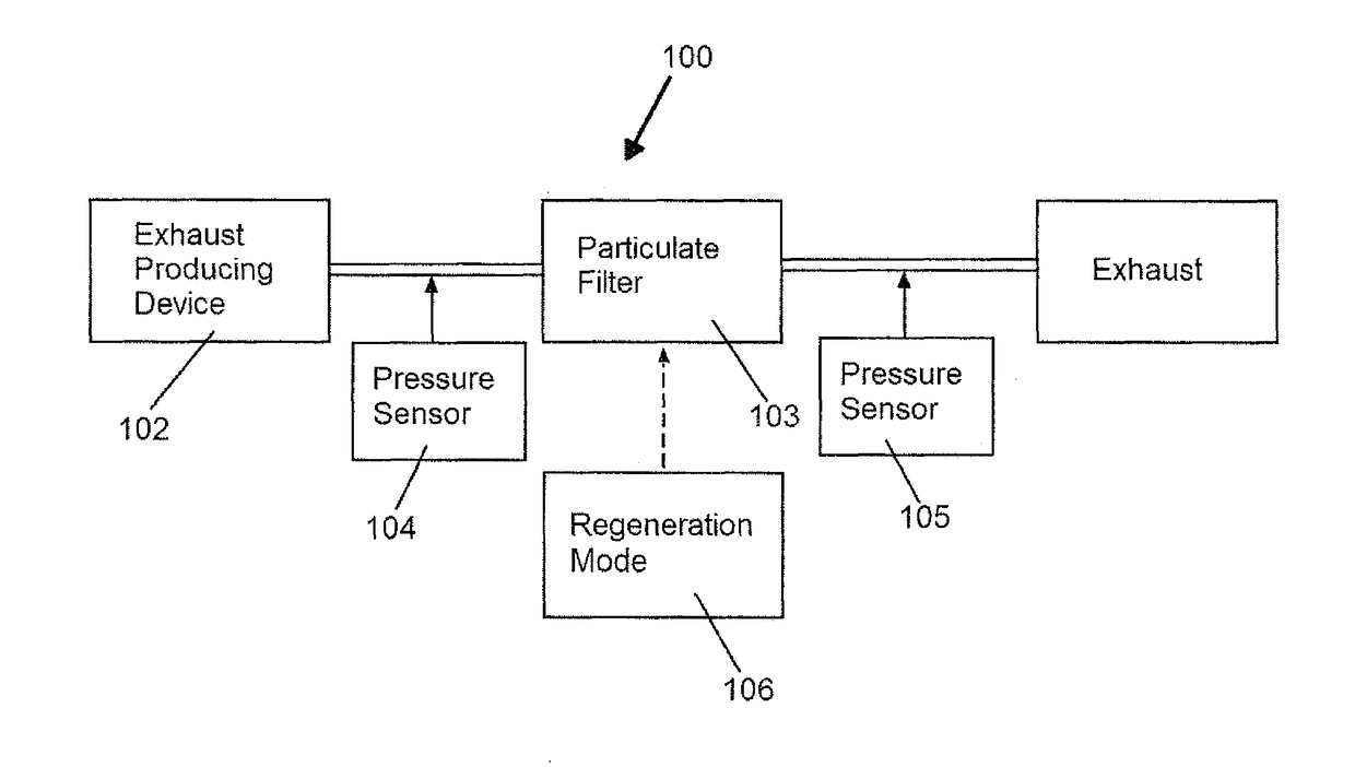
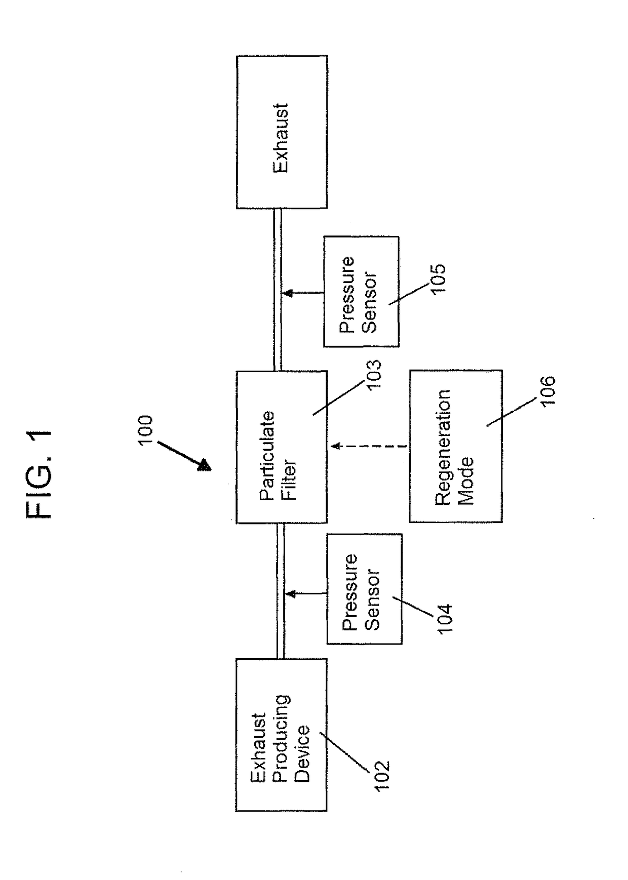
[0033]Turning now to FIG. 1, there is shown a schematic illustration of an exhaust emission control device according to the present invention, generally designated by reference numeral 100. The exhaust emission control device 100 includes a particulate filter 103 to filter out particles from exhaust gas which flows through the exhaust emission control device 100. The exhaust emission control device 100 can be a component of a drive device which includes an exhaust-producing device 102, such as an internal combustion engine, in addition to the exhaust emission control device 100.

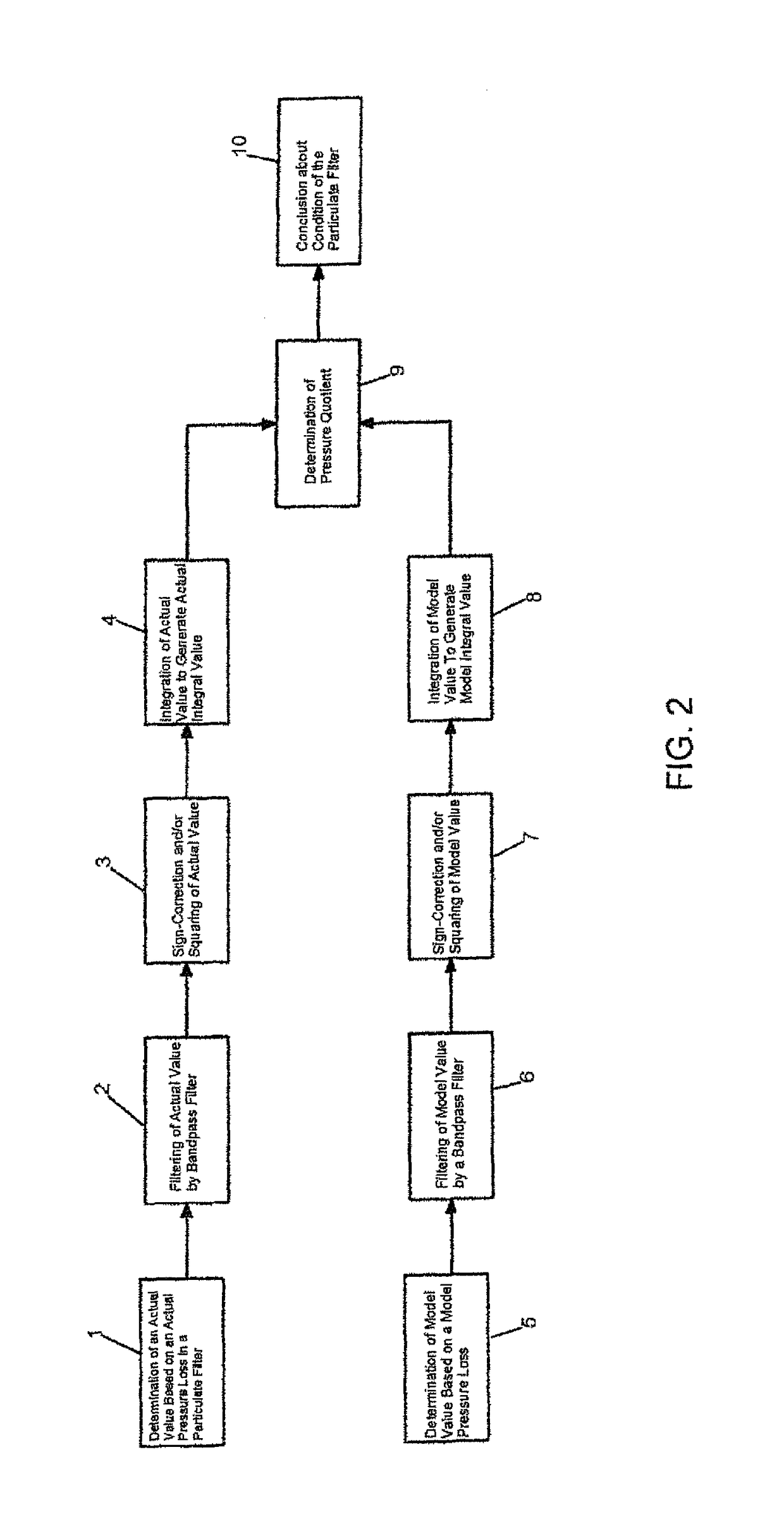
[0034]FIG. 2 shows a flow chart of a method ...


PUM


Abstract

In a method of operating an exhaust emission control device, the presence of an actual pressure loss of a particulate filter is determined, and a model pressure loss is determined as a function of a state variable. On the basis of the actual pressure loss and the model pressure loss a pressure quotient is determined and a condition of the particulate filter is ascertained in a diagnostic mode in response to the pressure quotient.

Description

CROSS-REFERENCES TO RELATED APPLICATIONS[0001]This application claims the priority of German Patent Application, Serial No. 10 2014 019 642.9, filed Dec. 31, 2014, pursuant to 35 U.S.C. 119(a)-(d), the disclosure of which is incorporated herein by reference in its entirety as if fully set forth herein.BACKGROUND OF THE INVENTION[0002]The present invention relates to a method of operating an exhaust emission control device, and to a corresponding exhaust emission control device.[0003]The following discussion of related art is provided to assist the reader in understanding the advantages of the invention, and is not to be construed as an admission that this related art is prior art to this invention.[0004]An exhaust emission control device finds application, for example, in a drive device, especially of a motor vehicle. The drive device has an exhaust-producing device, e.g. an internal combustion engine. Emission produced during operation of the drive device is emitted, normally to th...

Claims


Application Information

Patent Timeline
Patent Type & Authority Patents(United States)
IPC IPC(8): F01N11/00F01N3/021F01N3/023F01N9/00
CPCF01N11/00F01N3/021F01N9/002F01N11/002F01N3/023F01N9/005F01N2550/04F01N2550/24F01N2560/08F01N2560/14F01N2900/0404F01N2900/0418F01N2900/0422F01N2900/08F01N2900/1406F01N2900/1606Y02T10/47F01N11/005Y02T10/40
Inventor ODENDALL, BODO
Owner AUDI AG
Why Eureka
Try Eureka