Supercharge Your Innovation With Domain-Expert AI Agents!

Snap tap forming method and snap tap attaching tool used in the method

a technology of snapping taps and forming methods, which is applied in the direction of mechanical equipment, branching pipes, transportation and packaging, etc., can solve the problems of generating minute vibrations, leaking water through such rubbed portions or flaws, and not being able to accurately form holes of the same diameter in the existing pipe and the regeneration pipe respectively

Active Publication Date: 2017-08-01
YONE
View PDF19 Cites 6 Cited by
  • Summary
  • Abstract
  • Description
  • Claims
  • Application Information

AI Technical Summary

Benefits of technology

[0026]To overcome such drawbacks, there has been a demand for a technique by which holes having the same diameter can be formed in an existing pipe and a regeneration pipe with high accuracy by stationarily positioning and fixing the drill body thus bringing the drill body into a state where vibrations are not generated.
[0048]According to a fifth aspect of the invention, the saddle for mounting the gate valve is mounted on the snap tap forming portion of the water pipe by way of the band which surrounds the outer periphery of the water pipe, the mounting cylinder which is joined to the water flow sleeve of the gate valve is mounted on the outer peripheral surface of the saddle in a projecting manner, and the gate valve and the saddle are integrally connected with each other by the gate valve flange and the saddle flange. Accordingly, it is possible to guide water to the snap tap from the water pipe without causing leakage of water.

Problems solved by technology

However, in the above-mentioned patent literature 1, in forming a hole in a water pipe by inserting a drilling machine into a water flow passage in the inside of a body of a gate valve, there exists a drawback that a drill body of the drilling machine which is brought into contact with a hole forming portion of the regeneration pipe generates minute vibrations so that holes having the same diameter cannot be accurately formed in the existing pipe and the regeneration pipe respectively.
Further, clue to the vibrations of the drill body, there exists a drawback that a blade of a core drill is brought into contact with an outer peripheral wall surface of a saddle or the like so that rubbed portions or flaws are formed on a hole forming surface of a water diverting port or a portion around the hole forming surface.
Further, there also exists a possibility that water leaks through such rubbed portions or flaws.

Method used


Image

  • Snap tap forming method and snap tap attaching tool used in the method
  • Snap tap forming method and snap tap attaching tool used in the method
  • Snap tap forming method and snap tap attaching tool used in the method

Examples


embodiment 1

[Structure of Partition Wall of Gate Valve]

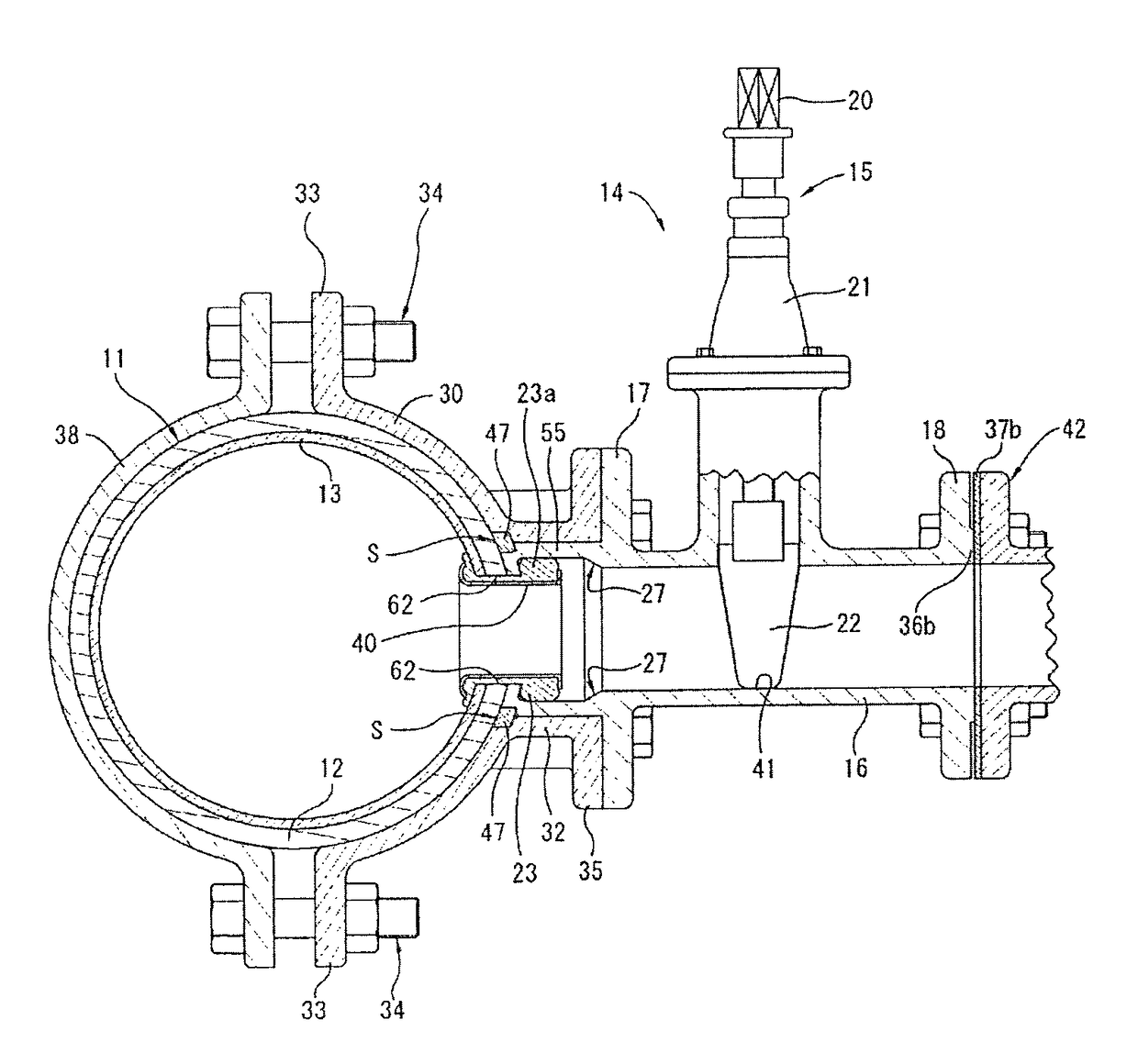
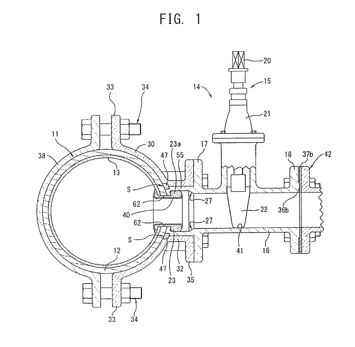
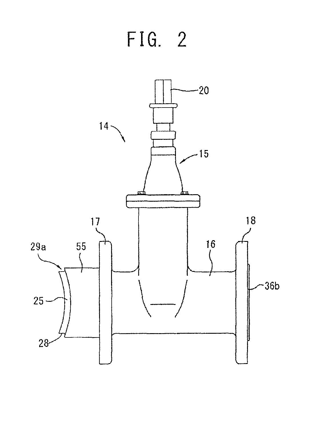
[0120]In this embodiment, the inflow opening portion 24 of the gate valve 15 is closed by a partition wall 25 which is formed along a curvature of an outer peripheral wall surface of the water pipe 11.

[0121]That is, the projecting cylinder 55 is mounted on the water flow sleeve 16 of the gate valve 15 in an extending manner and, as shown in FIG. 2 and FIG. 3, the projecting cylinder 55 is fitted in the mounting cylinder 32 of the saddle 30 as described later.

[0122]The projecting cylinder 55 constitutes a water guide passage for guiding water flowing in the water pipe 11 to the snap tap 14 in a branching manner.

[0123]A tapered inner diameter surface 27 is formed on the projecting cylinder 55, and the tapered inner diameter surface 27 has an inner diameter larger than an inner diameter of the water flow sleeve 16.

[0124]As shown in FIG. 3, the tapered inner diameter surface 27 is formed on a first flange 17 side.

[0125]With such a configuration...

embodiment 2

[0183]FIG. 11 is a cross-sectional view showing the whole structure of the water pipe 11 and the snap tap 14 according to the embodiment 2.

[0184]In this embodiment, as shown in FIG. 14, a partition wall is arranged at a center portion of a saddle 30, a snap tap 14 equipped with a gate valve 15 is fixed to a peripheral wall of the water pipe 11 by way of a saddle 30 and, thereafter, a drill body 44 (shown in FIG. 18) of a drilling machine 43 (shown in FIG. 18) is advanced into a water flow sleeve 16 of the gate valve 15 thus forming a hole in the partition wall of the saddle 30, a peripheral wall of an existing pipe 12, and a peripheral wall of a regeneration pipe 13 by drilling simultaneously. In this manner, the snap tap structure where the water pipe 11 and the snap tap 14 equipped with the gate valve 15 are integrally connected to each other is completed.

[0185]FIG. 12 is an explanatory view showing the whole structure of the snap tap 14 equipped with the gate valve 15.

[0186]FIG. ...

embodiment 3

[0216]Hereinafter, one example of a water diversion attaching tool according to this embodiment is explained with reference to drawing.

[0217]In the previously-mentioned embodiments 1 and 2, the explanation of the jig has been made with respect to the communicable connecting structure between the water pipe 11 and the gate vale 15 which constitutes the snap tap communicably connected to a lateral side wall of the water pipe with reference to the drawings. Unlike the explanation of the previously-mentioned embodiments 1 and 2, the jig of the embodiment 3 is explained as a jig which is used in a water diving port extending in a longitudinal direction with reference to FIG. 20 and subsequent drawings. That is, the explanation is made with respect to the case that a snap tap attaching tool is used in the vertical snap tap mounting structure where the snap tap is communicably connected to a horizontally-arranged water pipe 11 right above the water pipe 11, and a rubber packing 23 and a me...


PUM


Abstract

In a snap tap forming method, a partition wall formed along a curvature of a water pipe outer peripheral wall surface is brought into hermetical pressure contact with the water pipe outer peripheral wall and is mounted on the outer peripheral wall at a position corresponding to an inflow opening portion of a gate valve and at which a snap tap of the water pipe is formed. A center drill guide small hole aligned with the snap tap axis is drilled in a center portion of partition wall. A drilling machine inserted in a water flow sleeve of the gate valve is inserted into the aforementioned small hole. A water diverting port is formed in the partition wall and a peripheral wall of the water pipe using a core drill by advancing the drilling machine while estimating a drilling center. Then the drilling machine is removed from a water flow passage in the gate valve, and the snap tap is connected to the water diverting port by a snap tap attaching tool.

Description

BACKGROUND OF THE INVENTION[0001]The present invention relates to a technique on a snap tap forming method where a gate valve is fixedly attached preliminarily to a peripheral wall of a water pipe having a duplex pipe structure where a regeneration pipe (repair pipe) is fitted into a deteriorated pipe, a water diverting port is formed by drilling the peripheral wall of the water pipe having a duplex pipe structure by a drill body of the drilling machine which is advanceable and retractable in the inside of a water flow sleeve of the gate valve, and the snap tap equipped with the gate valve is attached to the water diverting port of the water pipe, and a snap tap attaching tool used in the method.[0002]Recently, water leakage troubles have frequently occurred along with the progress of deterioration of water pipe passages. Accordingly, it is necessary to dig out a deteriorated pipe which is an existing water pipe and to replace the deteriorated pipe with a new pipe. However, such an ...

Claims


Application Information

Patent Timeline
Patent Type & Authority Patents(United States)
IPC IPC(8): F16L41/06F16K1/12
CPCF16L41/06F16K1/12Y10T137/612
Inventor YONEDA, TOYOHIKOYONEDA, TETSUZODOMAN, NORIO
Owner YONE
Features
  • R&D
  • Intellectual Property
  • Life Sciences
  • Materials
  • Tech Scout
  • Unparalleled Data Quality
  • Higher Quality Content
  • 60% Fewer Hallucinations
Learn More