Development of a detection microsystem

a microsystem and detection technology, applied in the field of detection microsystems, can solve the problems of not being able to detect hidden contaminations, requiring the intervention of a qualified technician, and being relatively time-consuming and costly, and not enabling rapid and continuous measuremen

Active Publication Date: 2017-08-08
CENT SCI & TECHN DU BATIMET
View PDF4 Cites 2 Cited by
  • Summary
  • Abstract
  • Description
  • Claims
  • Application Information

AI Technical Summary

Benefits of technology

[0090]The device of the invention therefore has an advantage in terms of its size and makes it possible to considerably reduce the time interval between successive measurements and / or the response time of the measurement. The duration of a measurement with the device of the invention is typically 10 to 180 min, and preferably 30 to 120 min. Such a device therefore offers the possibility of implementing an effective strategy for monitoring fungal contaminations with a low time interval between measurements. Thus, an alert procedure can be envisaged in order to search for and treat contaminations in the earliest stages of development. Moreover, ambient air control systems, such as air handling units, can be slaved to the device of the invention in order to prevent or limit fungal development.

Problems solved by technology

Therefore, the usual methods rarely make it possible to detect hidden contaminations (growth behind a partition, in the building structure or in ventilation systems, for example) or recent contaminations, of which no signs of development are yet apparent.
These steps for detecting fungal contamination in an interior environment require the intervention of a qualified technician and are relatively time consuming and costly.
These analysis techniques do not therefore enable rapid and continuous measurement.
The solutions currently available do not therefore make it possible to satisfy the need for early detection and continuous monitoring of fungal contaminations.

Method used


Image

  • Development of a detection microsystem
  • Development of a detection microsystem
  • Development of a detection microsystem

Examples


first embodiment

Example 1: First Embodiment of the Device

[0125]The preconcentration module includes a micro-preconcentrator etched on a silicon plate by a DRIE process. The micro-preconcentrator is comprised of 20 grooves 6 cm long, with a rectangular cross-section 500 μm wide and 250 μm long, and has an effective volume of 0.15 cm3. The grooves are packed with resin particles based on 2,6-diphenyl oxide sold under the name TENAX® TA having an average diameter of 120 μm, a specific surface of 35 m2 / g, a porosity of 2.4 cm3 / g and an average pore size of 200 nm. The micro-preconcentrator is closed by a glass plate bonded to the surface comprising the grooves of the first plate.

[0126]A chromatographic microcolumn was etched on a silicon plate by a DRIE process. The microcolumn is comprised of a groove 5 m long, with a rectangular cross-section 150 μm wide and 200 μm long. The groove is produced in the form of parallel loops (or coils) having elbows in the form of an arc of circle so as to prevent the ...

example 2

on of the Microcolumn of the First Embodiment

[0129]For the calibration, the sensor array of the device of example 1 was replaced by a mass spectrometer.

[0130]The experimental parameters of the analysis chain are provided in table 1.

[0131]

TABLE 1Characteristics of the GC / MSParametersAnalysis conditionsThermal desorberTurboMatrix ATD (PerkinElmer)Desorption temperature370° C.Desorption rate50 mL / min Nitrogen N50Desorption time15 minCold trap temperature−30° C.(Tenax TA)Injection temperature300° C.(40° C. / s)Transfer line220° C.temperatureGas chromatograph / Autosystem XL / Mass spectrometerTurboMass(Perkin Elmer)MicrocolumnSylgard 184Vector gasHelium N60Constant pressure37.5 psiTemperature cycle40° C. for 2 min1° C. / min. to 41° C.Plateau for 2 min0.3° C. / min. to 44° C.for 2 min1° C. / min. to 47° C.Plateau for 2 minParameters of the massQuadrupole mode EI,spectrometerscanning (33-400)

[0132]Samples of the target VOCs were passed into the microcolumn to determine the retention time of each tar...

example 3

tal Methods

3.1 Experimental Device for Polymer Sensors

3.1.A Data Acquisition System

[0135]The experiments were conducted using a system enabling the acquisition of signals from a card comprised of conductive polymers constituting the core of the system.

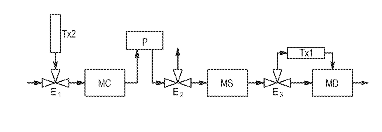
[0136]The emission chambers are placed outside of the system. A filtration system comprised of a TENEX tube Tx is located upstream of the emission chamber and ensures “clean” air renewal (leakage). Downstream, a PTFE tube enables the connection between the emission chamber and a 3-way solenoid valve. All of the connections are also made of PTFE. The 3-way solenoid valve (sold by the BIO-CHEM-VALVE CORP) makes it possible to select a reference path (air filtered on activated carbon), a sampling path (emission chamber) or a cleaning path (1-butanol / water mixture).

[0137]A pump (sold by the ESCAP company) makes it possible to transfer air of different climates at 147±1 mL / min−1 toward the sensor array confined n a PTFE chamber (internal di...


PUM

PropertyMeasurementUnit
surface areasaaaaaaaaaa
pore sizeaaaaaaaaaa
sizeaaaaaaaaaa

Abstract

This invention relates to a device for detecting fungal contamination in an interior environment, including:a concentration module (MC);a separation module (MS) including a chromatographic microcolumn; anda detection module (MD),characterized in that it includes at least one first solenoid valve (E3) upstream of the detection module (MD) enabling either to direct a flow containing target molecules toward the detection module (MD), or to direct a flow filtered by a first means for filtering (Tx1), enabling the detection module (MD) to be cleaned when the flow does not contain the target molecules. The invention also relates to a control interface of the device.

Description

TECHNICAL FIELD OF THE INVENTION[0001]This invention relates to a device for detecting fungal contamination in an interior environment, the use thereof as well as a process for detecting fungal contamination in an interior environment implementing such a device.[0002]Individuals in industrialized countries spend more than 90% of their time in closed spaces where they are exposed to numerous physical, chemical and biological pollutants. Aware of the health risks potentially caused by this complex pollution, public authorities have introduced, in the Grenelle 2 environmental code, the principle of monitoring air quality in interior environments. This principle includes the implementation of systems for measuring and providing information in establishments receiving vulnerable people (children, elderly people, etc.), and in places open to the public (schools, public transport, museums, etc.). Thus, as noted by the World Health Organization (WHO) in its report published in 2009 “WHO gui...

Claims


Application Information

Patent Timeline
Patent Type & Authority Patents(United States)
IPC IPC(8): C12Q1/04G01N33/00
CPCC12Q1/04G01N33/0029G01N33/0047
Inventor MOULARAT, STEPHANEJOBLIN, YAELROBINE, ENRIC
Owner CENT SCI & TECHN DU BATIMET
Why Eureka
Try Eureka