Substrate cleaning method and substrate cleaning apparatus

a cleaning apparatus and substrate technology, applied in the direction of photomechanical treatment, cleaning using liquids, instruments, etc., can solve the problems of reducing the cleaning force of the under surface, unable to achieve the desired particle removal rate, and the supply of liquid from the ultrasonic cleaning nozzle is also limited, so as to reduce the intensity of the physical force applied to the particle to separate the particle from the principal surface of the substrate, the effect of removing fine particles

Active Publication Date: 2017-08-08
DAINIPPON SCREEN MTG CO LTD
View PDF14 Cites 0 Cited by
  • Summary
  • Abstract
  • Description
  • Claims
  • Application Information

AI Technical Summary

Benefits of technology

[0011]In the apparatus described in JP2013-84667A, the entire top surface and under surface of the substrate are cleaned by supplying the degassed treatment liquid and applying ultrasonic vibration to this treatment liquid. In this way, damage on the pattern elements of the substrate is suppressed. However, since the under surface is cleaned by the degassed treatment liquid as the top surface is, a cleaning force for the under surface is reduced and fine particles cannot be removed on the under surface as compared with the case where the treatment liquid is not degassed, with the result that it may not be possible to achieve a desired particle removal rate.
[0014]The invention was developed in view of the above problems and aims to provide a substrate cleaning method and a substrate cleaning apparatus capable of preventing the collapse of pattern elements on one principal surface by cavitation and satisfactorily cleaning another surface of the substrate in an ultrasonic cleaning treatment for cleaning the substrate by removing contaminants adhering to the substrate under surface by ultrasonic waves.
[0017]According to the invention, it is possible to prevent the collapse of pattern elements on one principal surface of a substrate by cavitation and satisfactorily clean another principal surface of the substrate in the ultrasonic cleaning treatment for cleaning the substrate by removing contaminants adhering to the substrate under surface (other principal surface) by ultrasonic waves.

Problems solved by technology

However, since the under surface is cleaned by the degassed treatment liquid as the top surface is, a cleaning force for the under surface is reduced and fine particles cannot be removed on the under surface as compared with the case where the treatment liquid is not degassed, with the result that it may not be possible to achieve a desired particle removal rate.
Thus, the part where the supply of the liquid from the ultrasonic cleaning nozzle is directly received is also limited to a specific position on the under surface of the substrate.
Therefore, in the method of JP2010-27816A, it may not be possible to sufficiently remove particles on the entire under surface of the substrate.
Further, cooling gas needs to be supplied to the liquid film to perform the freezing and an increase of running cost is unavoidable.

Method used


Image

  • Substrate cleaning method and substrate cleaning apparatus
  • Substrate cleaning method and substrate cleaning apparatus
  • Substrate cleaning method and substrate cleaning apparatus

Examples


first embodiment

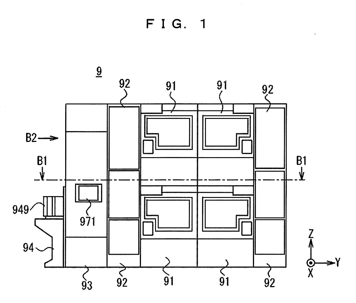
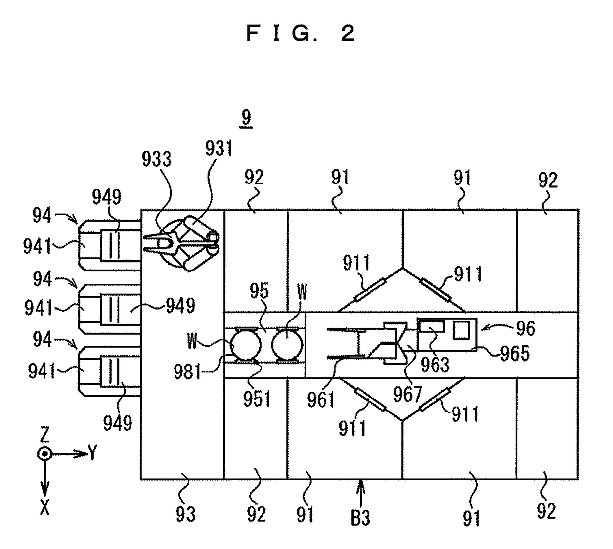
[0041]FIGS. 1, 2 and 3 are diagrams showing a schematic construction of a substrate processing apparatus 9 according to this invention. FIG. 1 is a front view of the substrate processing apparatus 9, FIG. 2 is a sectional view taken along a line B1-B1 indicted by arrows of the substrate processing apparatus 9 in FIG. 1. FIG. 3 is a side view of the substrate processing apparatus 9 in FIG. 1 when viewed in a direction of an arrow B2. This apparatus is a single-substrate processing apparatus used in a cleaning process for removing contaminants such as particles (hereinafter, referred to as “particles and the like”) adhering to a substrate W such as a semiconductor substrate (hereinafter, merely referred to as a “substrate W”).

[0042]Note that a coordinate system with a Z axis extending in a vertical direction and an XY plane as a horizontal plane is appropriately attached to the respective drawings to make a directional relationship clear. Further, in each coordinate system, a pointing...

second embodiment

[0219]In the first embodiment, the nozzle 350 is relatively moved with respect to the substrate W by the swiveling of the nozzle 350 including the single discharge port 352 and the rotation of the substrate W itself. By this relative movement, the directly transmitted area BE is successively located on the entire substrate under surface Wb. There is no limitation to this in carrying out the invention and the nozzle 350 may be relatively moved with respect to the substrate W by driving only either one of the nozzle 350 and the substrate W. For example, by providing a nozzle 350 including a plurality of discharge ports 352, a plurality of directly transmitted areas BE may be created during the ultrasonic cleaning process and the plurality of directly transmitted areas BE may be moved only by the rotation of the substrate W without moving the nozzle 350 during the ultrasonic cleaning process.

[0220]FIG. 19 shows the configuration of a second liquid discharge unit according to a second e...

third embodiment

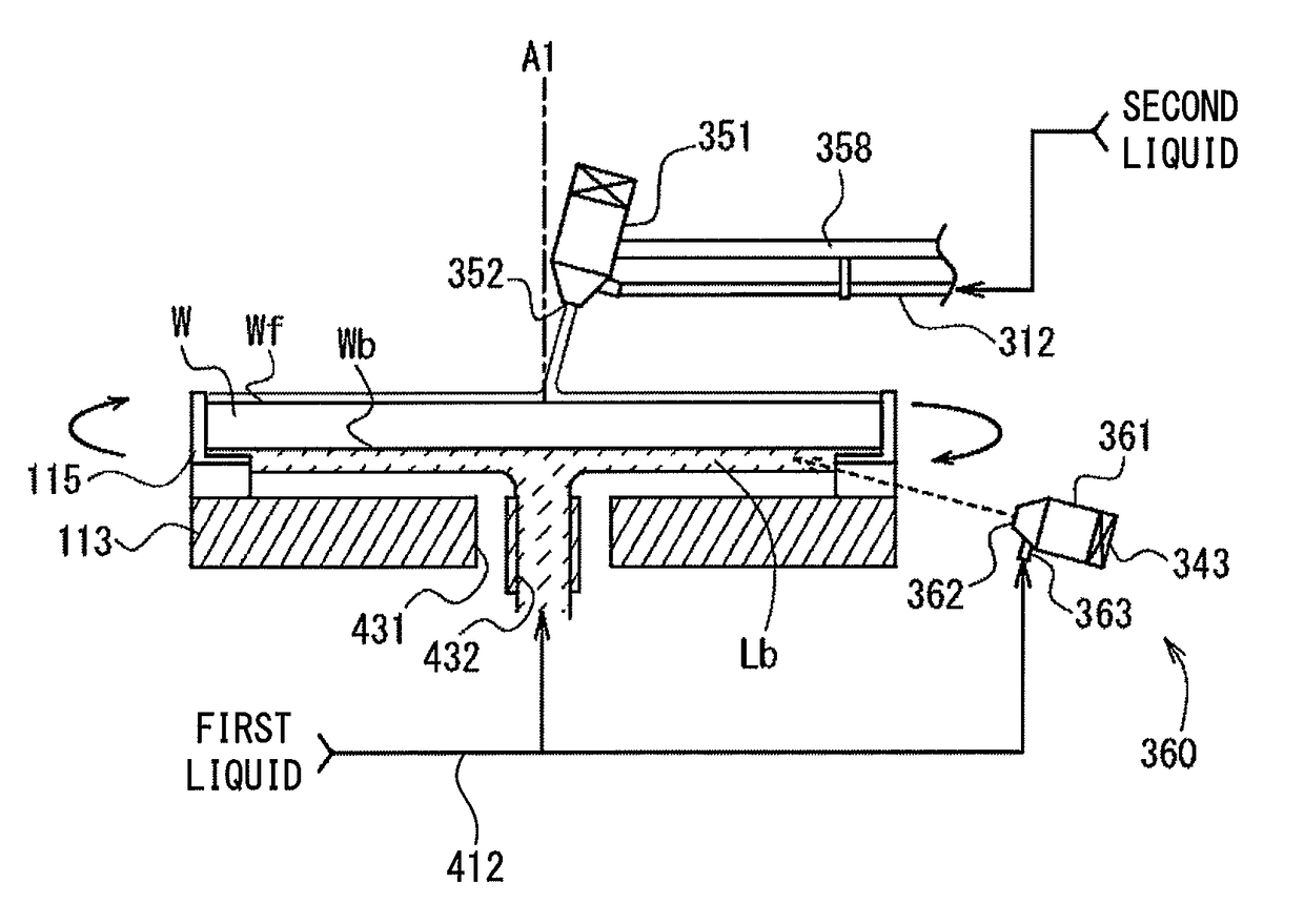
[0231]In the first and second embodiments, ultrasonic vibration is transmitted to the substrate under surface Wb and the liquid film Lb via the substrate W by supplying the ultrasonic wave applying liquid only to the substrate top surface Wf. However, there is no limitation to the above embodiments in carrying out the invention and the ultrasonic wave applying liquid obtained by applying ultrasonic waves to the second liquid may be supplied to the substrate top surface Wf using the nozzle 350 in the first or second embodiment and a nozzle (nozzle 360) may be provided to directly supply the ultrasonic wave applying liquid to the substrate under surface Wb.

[0232]If such a configuration is adopted, ultrasonic vibration can be applied to the substrate W from both the substrate top surface Wf and the substrate under surface Wb, wherefore a particle cleaning force on the substrate under surface Wb becomes stronger and more satisfactory cleaning of the substrate under surface Wb than in th...


PUM

PropertyMeasurementUnit
distanceaaaaaaaaaa
widthaaaaaaaaaa
widthaaaaaaaaaa

Abstract

An ultrasonic wave applying liquid is supplied to one principal surface of a substrate while a liquid film of a first liquid being formed on another principal surface of the substrate. The ultrasonic wave applying liquid is obtained by applying ultrasonic waves to a second liquid. Ultrasonic vibration is transmitted to the other principal surface and the liquid film, thereby ultrasonically cleaning the other principal surface. The first liquid has a higher cavitation intensity, which is a stress per unit area acting on the substrate by cavitation caused in the liquid when ultrasonic waves are transmitted to the liquid present on the principal surface of the substrate, than the second liquid.

Description

CROSS REFERENCE TO RELATED APPLICATION[0001]The disclosure of Japanese Patent Application enumerated below including specification, drawings and claims is incorporated herein by reference in its entirety: No. 2014-185758 filed on Sep. 12, 2014.BACKGROUND OF THE INVENTION[0002]1. Field of the Invention[0003]The invention relates to a substrate cleaning apparatus and a substrate cleaning method of cleaning a substrate that has one principal surface on which pattern elements are formed and another principal surface to be cleaned. Note that substrates to be cleaned include semiconductor wafers, glass substrates for photo mask, glass substrates for liquid crystal display, glass substrates for plasma display, substrates for FED (Field Emission Display), substrates for optical disc, substrates for magnetic disc, substrates for opto-magnetic disc and various other substrates.[0004]2. Description of the Related Art[0005]A process of manufacturing an electronic component such as a semiconduct...

Claims


Application Information

Patent Timeline
Patent Type & Authority Patents(United States)
IPC IPC(8): B08B3/12H01L21/02C11D11/00G03F1/82H01L21/67
CPCH01L21/02057B08B3/12C11D11/007C11D11/0047G03F1/82H01L21/67051B08B2203/0288
Inventor HANAWA, YOSUKEMIYA, KATSUHIKOSASAKI, YUTA
Owner DAINIPPON SCREEN MTG CO LTD
Why Eureka
Try Eureka