Metallic separator for fuel cell and manufacturing method therefor

a fuel cell and separator technology, applied in the direction of cell components, final product manufacturing, sustainable manufacturing/processing, etc., can solve the problems of repeated stresses increased surface pressure between the electrode assembly and the separator, etc., to reduce the effect of metal consumption, reducing contact resistance, and suppressing damage in the electrode assembly

Inactive Publication Date: 2005-05-05
HONDA MOTOR CO LTD
View PDF3 Cites 3 Cited by
  • Summary
  • Abstract
  • Description
  • Claims
  • Application Information

AI Technical Summary

Benefits of technology

[0021] According to the invention, conductive inclusions are exposed on the surface with corrosion resistance, and metal is precipitated selectively on the exposed conductive inclusions, and therefore damage in the electrode assembly is suppressed, the reducing effect of contact resistance by metal can be opened up to the full extent, and the metal consumption is reduced and the cost can be reduced.

Problems solved by technology

As a result, the electrode assembly is expanded and swollen, and the surface pressure at the electrode assembly and separator is increased.
Thus, by the cycles of power generation and stopping, repetitive stresses occur between the electrode assembly and separator.
Therefore, by the repetitive stresses occurring between the electrode assembly and separator, the surface of the electrode assembly is damaged, whereby the contact resistance between the separator and electrode assembly is increased, resulting in degrading the current collecting function of the separator.
However, there is a problem in that the gold consumption is too great, and it is expensive.
However if the gold plating has defects such as pin holes, the nickel which is a component in the treatment for substrate may elute.
Elution of nickel lowers the performance, for example, the ion exchange capacity of the electrolyte membrane, and further leads to other problems such as peeling of gold plating or increase in contact resistance.

Method used


Image

  • Metallic separator for fuel cell and manufacturing method therefor
  • Metallic separator for fuel cell and manufacturing method therefor
  • Metallic separator for fuel cell and manufacturing method therefor

Examples


embodiment 1

Preferred Embodiment 1

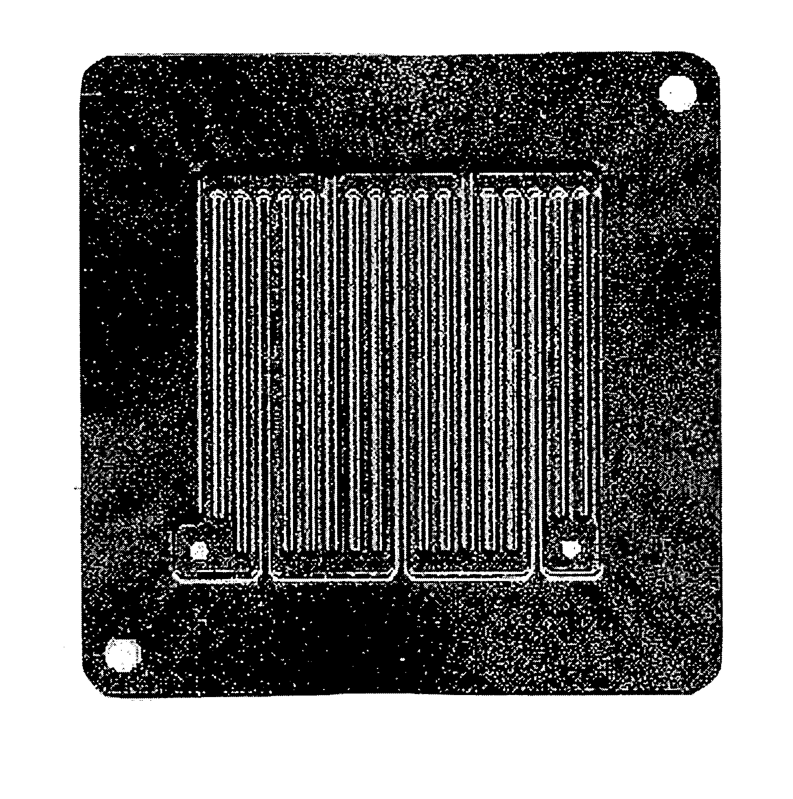
[0038] An austenitic stainless steel plate having the composition shown in Table 1 was rolled to a thickness of 0.2 mm, and a necessary number of square sheets of 100 mm×100 mm were cut out from the rolled steel. These thin sheets were press-formed, and a material plate for a separator as shown in FIG. 1 was obtained. This material plate has a power generating part in corrugated-section in the center, and has a flat edge in the periphery of the power generating part. In this material plate, B in component is precipitated in the metal structure as M2B and MB type boride and M23(C,B)6 type boride, and these borides are conductive inclusions forming conductive paths on the separator surface.

TABLE 1(wt %)CSiMnPSCuNiCrMoNbTiAlNB0.0730.280.130.0150.0010.1110.120.92.03——0.080.0300.60

[0039] Furthermore, both sides of the material plate were passivated, whereby firm oxide films were formed on the surface of parent metal. For passivation, the material plate was degreas...

embodiment 2

Preferred Embodiment 2

[0040] Six types of separators of preferred embodiment 2 were obtained under the same conditions as in preferred embodiment 1 except that copper plating was performed instead of silver plating. In each separator of preferred embodiment 2 also, conductive inclusions protruded at the surface. For copper plating, the material plate was immersed in a plating bath (pH 11) made by copper (I) cyanide (20 g / L), free sodium cyanide (25 g / L), sodium carbonate (20 g / L), potassium hydroxide (0.5 g / L), and Rochelle salt (15 g / L) held at 40° C. with current density set at 0.8 A / dm2. In this case, the immersion time was set in six periods, that is, 1, 2, 3, 4, 7, and 10 minutes, and the copper amount per unit area increased as the immersion time was increased. After copper plating, the material plate was washed by water in ordinary temperature twice for 10 minutes each time.

embodiment 3

Preferred Embodiment 3

[0041] Six types of separators of preferred embodiment 3 were obtained under the same conditions as in preferred embodiment 1 except that nickel plating was performed instead of silver plating. In each separator of preferred embodiment 3 also, conductive inclusions protruded at the surface. For nickel plating, the material plate was immersed in a plating bath (pH 5.5) made by nickel sulfate (250 g / L), nickel chloride (38 g / L), boric acid (30 g / L), cobalt sulfate (12 g / L), and formalin (1.5 g / L) held at 40° C. with current density set at 0.8 A / dm2. In this case, the immersion time was set in six periods, that is, 1, 2, 3, 4, 7, and 10 minutes, and the nickel amount per unit area increased as the immersion time was increased. After nickel plating, the material plate was washed by water in ordinary temperature twice for 10 minutes each time.


PUM

PropertyMeasurementUnit
temperaturesaaaaaaaaaa
thicknessaaaaaaaaaa
thicknessaaaaaaaaaa

Abstract

A metallic separator for a fuel cell (and a manufacturing method therefore) can reduce damage to an electrode assembly, open up the maximum capacity of the reducing effect of contact resistance due to coating of gold by gold plating or the like, and reduce consumption of gold to lower the cost. Conductive inclusions are exposed at the surface with corrosion resistance, and at least one kind of metal or an alloy thereof selected from silver, copper, nickel, and tin is precipitated on the exposed conductive inclusions. From the viewpoint of reducing contact resistance, the conductive inclusions preferably protrude from the separator surface.

Description

BACKGROUND OF THE INVENTION [0001] 1. Field of the Invention [0002] The present invention relates to a metallic separator for a solid high polymer type fuel cell, and relates to a manufacturing method therefor. [0003] 2. Description of the Related Art [0004] A solid high polymer type fuel cell is formed as a fuel cell stack by laminating a plurality of units, one unit being a laminated body having separators laminated on both sides of a flat electrode assembly (MEA: Membrane Electrode Assembly). The electrode assembly has a three-layer structure having an electrolyte membrane made of ion exchange resin or the like enclosed between a pair of gas diffusion electrodes composing a positive electrode (cathode) and a negative electrode (anode). The gas diffusion electrodes have gas diffusion layers formed at the outside of an electrode catalyst layer contacting with the electrode membrane. The separators are laminated so as to contact with the gas diffusion electrodes of the electrode ass...

Claims


Application Information

Patent Timeline
Patent Type & Authority Applications(United States)
IPC IPC(8): H01M8/02B05D5/12B32B15/01B32B15/20H01M8/10
CPCB32B15/01B32B15/015B32B15/018C25D5/02H01M8/0206Y10T428/12903H01M8/0228Y02E60/50Y10T428/12944Y10T428/12896Y10T428/12708H01M8/0223Y02P70/50
Inventor TSUJI, MAKOTOINOUE, MASAJIROUTSUNOMIYA, MASAOOTANI, TERUYUKIKUWAYAMA, TAKASHITAKAI, TAKAHIRO
Owner HONDA MOTOR CO LTD
Why Eureka
Try Eureka