Relief valve

a relief valve and valve body technology, applied in the field of relief valves, can solve the problems of excessive oscillation of relief valves, the seat pressure of many prior art relief valves is substantially lower than the cracking pressure, etc., and achieves the effects of reducing cross-sectional, minimizing possible oscillations, and increasing flow ra

Active Publication Date: 2017-08-15
HALKEY ROBERTS CORP
View PDF13 Cites 5 Cited by
  • Summary
  • Abstract
  • Description
  • Claims
  • Application Information

AI Technical Summary

Benefits of technology

[0011]For the purpose of summarizing this invention, this invention comprises a relief valve having a crenelated exhaust ring surrounding the poppet. The crenelated exhaust ring comprises a series of alternating crenels and merlons which together define an increasing cross-sectional exhaust area circumferentially about the poppet during cracking (i.e., once the pressure in the inflatable device exceeds the cracking pressure) as the poppet rises in the relief valve in response to increased pressures and, conversely, a decreasing cross-sectional exhaust area about the poppet during closing as the poppet lowers to its re-seated, sealed position. Moreover, the particular design of the crenels in the form of a larger upper cross-sectional area to a smaller lower cross-sectional opening, advantageously achieves a reseating pressure that is substantially equal to or slightly less than the cracking pressure while minimizing possible oscillations during re-seating of the poppet. Finally, the crenelated exhaust ring surrounding the poppet advantageously results in a relief valve having a higher flow rate at a given back pressure than would be achieved without the crenelated exhaust ring surrounding the poppet.

Problems solved by technology

Unfortunately, however, the reseat pressure of many prior art relief valves is substantially lower than the cracking pressure.
Moreover, some relief valves suffer from excessive oscillations during opening or closing, which in extreme situations could self-dissemble or otherwise come part.

Method used


Image

  • Relief valve
  • Relief valve
  • Relief valve

Examples


Embodiment Construction

[0028]The following description is of the best mode presently contemplated for carrying out the invention. This description is not to be taken in a limiting sense, but is made merely for the purpose of describing one or more preferred embodiments of the invention. The scope of the invention should be determined with reference to the claims.

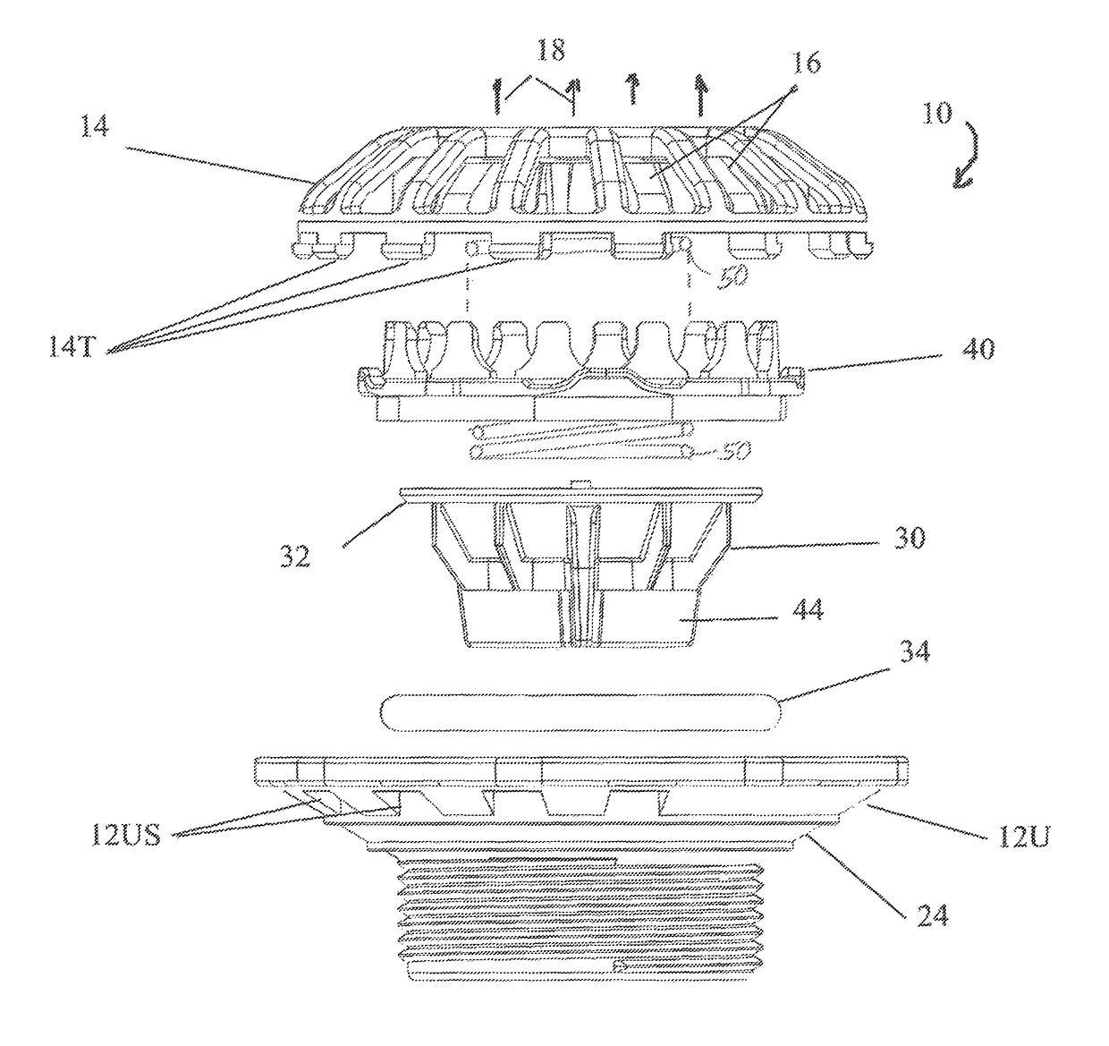
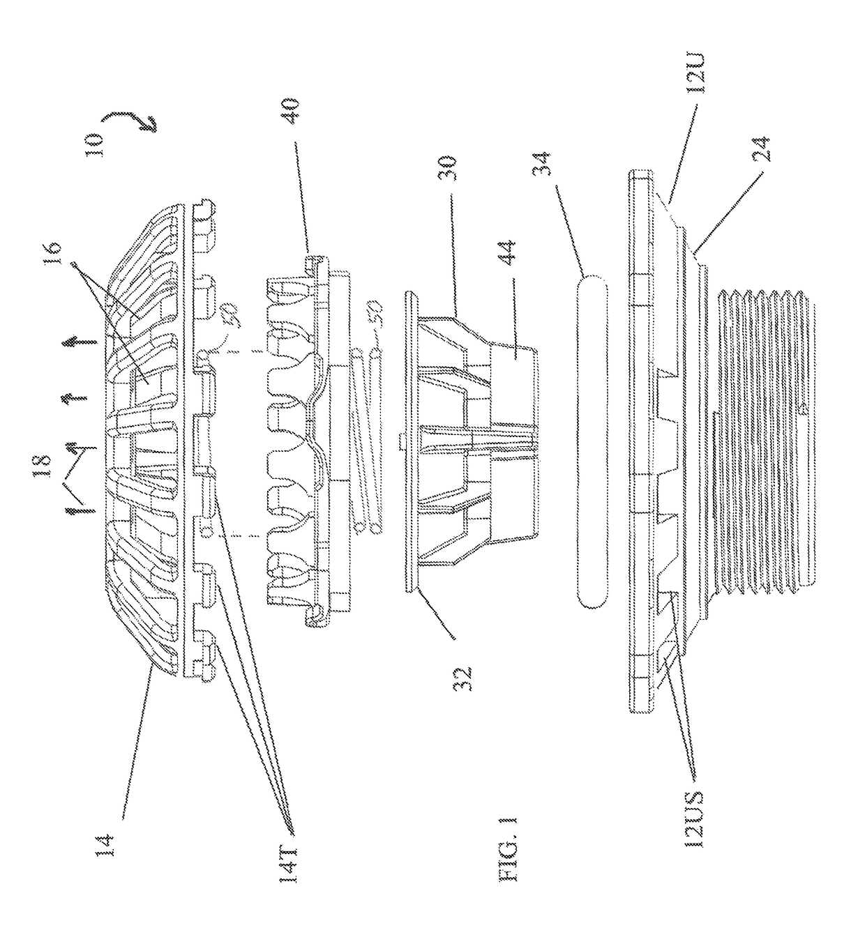
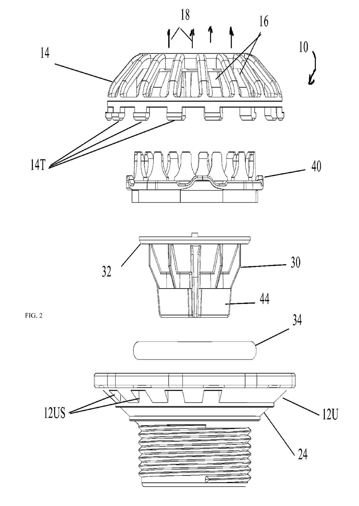
[0029]The present invention is an improvement of U.S. Pat. Nos. 7,469,713 and 7,096,884, the disclosures of which are each hereby incorporated by reference herein. Similar to these earlier embodiments in these patents and using similar reference numerals where appropriate as shown in FIGS. 1-4, the relief valve 10 of the invention comprises an upper body 12U and a lower body (not shown) threadably coupled together by complementary respective threads (see FIG. 12). A cap 14 is coupled to the upper body 12U. Cap 14 comprises a plurality of flow openings 16 about its periphery allowing internal fluid such as air to flow through the relief valve 10 to...


PUM


Abstract

A relief valve having a crenelated exhaust ring surrounding the poppet. The crenelated exhaust ring comprises a series of alternating crenels and merlons which together define an increasing cross-sectional exhaust area circumferentially about the poppet during cracking (i.e., once the pressure in the inflatable device exceeds the cracking pressure) as the poppet rises in the relief valve in response to increased pressures and, conversely, a decreasing cross-sectional exhaust area about the poppet during closing as the poppet lowers to its re-seated, sealed position. The design of the crenels in the form of a larger upper cross-sectional area to a smaller lower cross-sectional opening, advantageously achieves a reseating pressure that is substantially equal to or slightly less than the cracking pressure while minimizing possible oscillations during re-seating of the poppet. The crenelated exhaust ring surrounding the poppet advantageously results in a relief valve having a higher flow rate at a given back pressure than would be achieved without the crenelated exhaust ring surrounding the poppet.

Description

CROSS-REFERENCE TO RELATED INVENTIONS[0001]This application claims the benefit of provisional patent application, Ser. No. 61 / 813,599, filed Apr. 18, 2013, the disclosure of which is hereby incorporated by reference herein.BACKGROUND OF THE INVENTION[0002]This invention relates to relief valves. More particularly, this invention relates to relief valves having similar cracking and reseat pressures.DESCRIPTION OF THE BACKGROUND ART[0003]Presently, there exist many types of check valves designed to allow the flow of a fluid such as a gas in one direction but to block or “check” the flow of the fluid in the opposite direction. The amount of fluid force required to open the poppet of the valve in the un-checked direction is often referred to as the cracking pressure. Typically, the cracking pressure of a check valve is determined by the spring force and spring constant of the internal spring that constantly urges the poppet into a sealing position until unseated therefrom once the crack...

Claims


Application Information

Patent Timeline
Patent Type & Authority Patents(United States)
IPC IPC(8): F16K17/04F16K47/08F16K27/02F16K15/02
CPCF16K17/0433F16K15/028F16K27/0209F16K47/08Y10T137/7739
Inventor FAWCETT, LYMAN
Owner HALKEY ROBERTS CORP
Why Eureka
Try Eureka