
Conductive sheet including mesh pattern having improved visibility for observation, and touch panel and display device including the same

a technology of conductive sheets and mesh patterns, which is applied in the direction of identification means, instruments, other domestic objects, etc., can solve the problems of reducing the current transmission rate between electrodes, the time until the contact position is detected after touching the touch panel (that is, the response speed increases), and the increase in the response speed, so as to suppress the generation of both the granular feeling of noise and color noise, and improve the visibility of the object for observation. , the effect of suppressing the generation

Active Publication Date: 2017-08-15
FUJIFILM CORP
View PDF16 Cites 6 Cited by
  • Summary
  • Abstract
  • Description
  • Claims
  • Application Information

AI Technical Summary

Benefits of technology

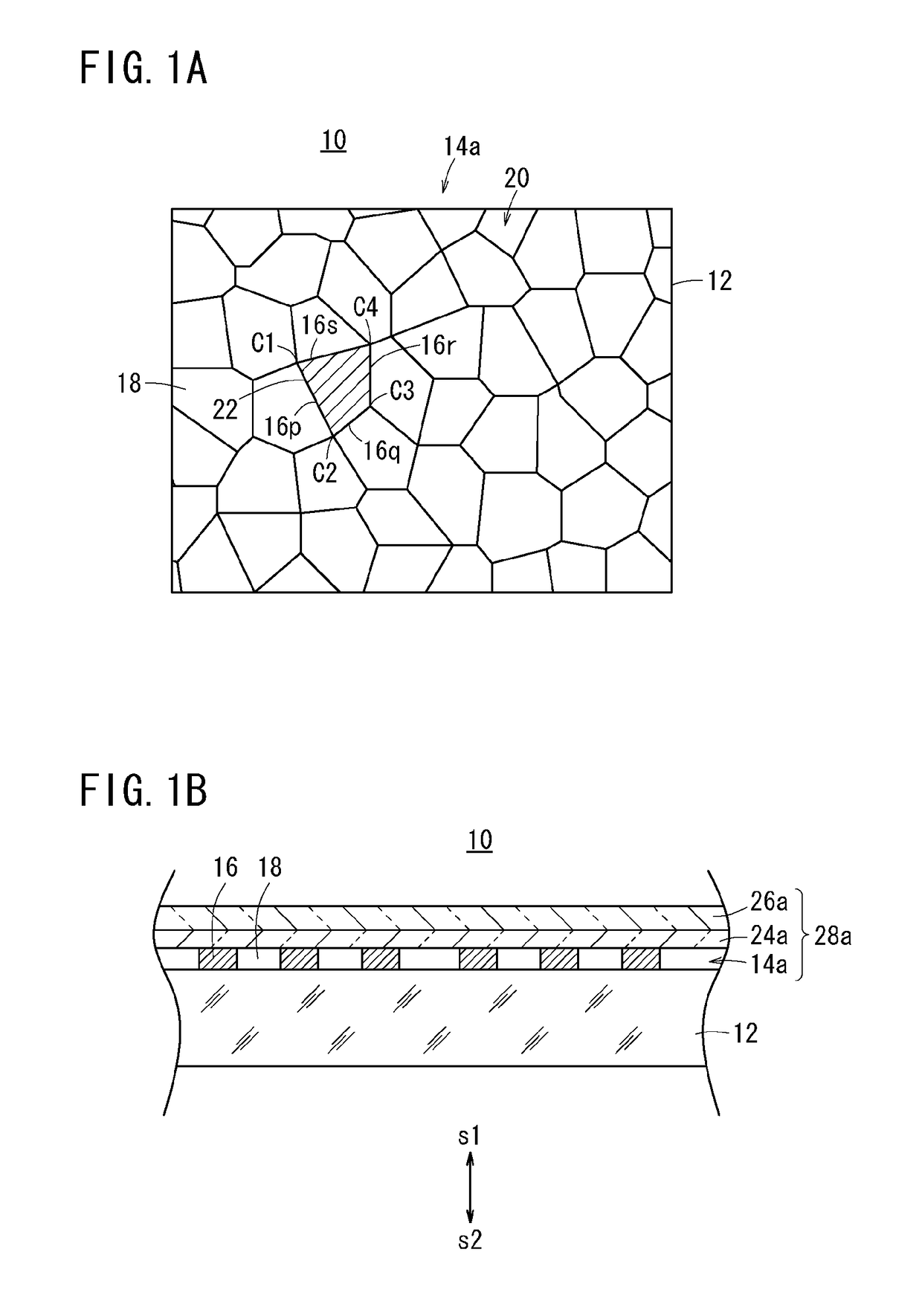
[0010]The present invention has been made in order to solve the above-described problem, and it is an object of the present invention to provide a conductive sheet, a touch panel, and a display device capable of greatly improving the visibility of an object for observation while suppressing the generation of both the granular feeling of noise and color noise.
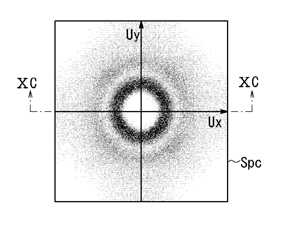
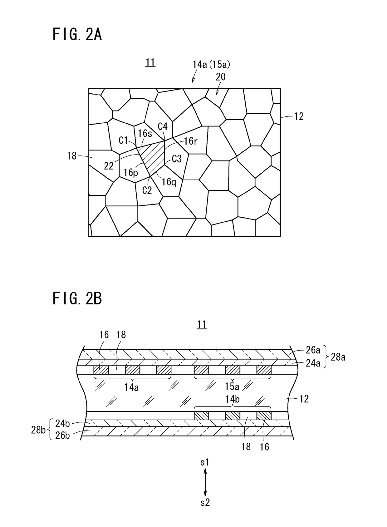
[0012]As described above, the standard deviation of an area of each opening of the mesh pattern is set to be equal to or greater than 0.017 mm2 and equal to or less than 0.038 mm2. By adjusting the area distribution of the openings to fall within the range, generation of color noise can also be suppressed, and the visibility of an object for observation can be greatly improved.
[0024]According to the present invention, since it is possible to suppress the generation of both the granular feeling of noise and color noise, it is possible to greatly improve the visibility of the object for observation.
[0025]That is, according to the conductive sheet, the touch panel, and the display device of the present invention, the standard deviation of the area of each opening of a mesh pattern is adjusted to fall within the range of 0.017 mm2 or more and 0.038 mm2 or less, the standard deviation for the root mean square deviation of the centroid positions, which are disposed along a predetermined direction in the two-dimensional distribution of the centroid positions of the openings, with respect to a direction perpendicular to the predetermined direction is adjusted to fall within the range of 15.0 μm or greater, or the standard deviation over the radial direction of the value expressed by the common logarithm of the standard deviation along the angular direction in the power spectrum of the mesh pattern is adjusted to fall within the range of 0.965 or more and 1.065 or less. Therefore, it is possible to suppress the generation of both the granular feeling of noise and color noise, and thus it is possible to greatly improve the visibility of the object for observation.

Problems solved by technology

As a result, since the transmission rate of the current between electrodes is reduced, a problem that the time until the contact position is detected after touching the touch panel (that is, response speed) increases becomes noticeable.
However, when the sizes of openings determined by the mesh shapes are approximately same like in the mesh pattern 4 disclosed in US 2011 / 0102361 A, color noise has been generated in some cases due to the relationship with the regularity of the arrangement of respective subpixels (for example, RGB subpixels) of a pixel.
When the sizes of the openings are excessively vary like in the case of the mesh pattern 8 disclosed in US 2009 / 0219257 A, there is a disadvantage in that granular feeling of noise (also referred to as feeling of roughness) is easily recognized.

Method used


Image

  • Conductive sheet including mesh pattern having improved visibility for observation, and touch panel and display device including the same
  • Conductive sheet including mesh pattern having improved visibility for observation, and touch panel and display device including the same
  • Conductive sheet including mesh pattern having improved visibility for observation, and touch panel and display device including the same

Examples


examples

[0396]Hereinafter, the present invention will be described more specifically by way of examples of the present invention. In the present invention, materials, amounts, ratios, processings, processing procedures, and the like shown in the following examples can be appropriately modified without departing from the gist of the present invention. Therefore, the scope of the present invention should not be construed as being limited by the examples shown below.

[0397]The visibility (moire, granular feeling of noise, and color noise) in the display device 40 including the conductive sheet 11 of examples 1 to 21 and comparative examples 1 and 2 was evaluated.


PUM

PropertyMeasurementUnit
areaaaaaaaaaaa
areaaaaaaaaaaa
areaaaaaaaaaaa

Abstract

In the mesh pattern of the conductive sheet of the invention in which openings having different shapes are arrayed in plan view, a standard deviation of an area of each of the openings is equal to or greater than 0.017 mm2 and equal to or less than 0.038 mm2, in a two-dimensional distribution of centroid positions of the openings; a standard deviation for a root mean square deviation of each of the centroid positions which are disposed along a predetermined direction, with respect to a direction perpendicular to the predetermined direction is equal to or greater than 15.0 μm; or a standard deviation over a radial direction of a value expressed by a common logarithm of a standard deviation along an angular direction in a power spectrum of the mesh pattern is equal to or greater than 0.965 and equal to or less than 1.065.

Description

CROSS REFERENCE TO RELATED APPLICATIONS[0001]This application is a continuation application of International Application PCT / JP2012 / 075450 filed on Oct. 2, 2012, which claims priority under 35 U.S.C. 119(a) to Application No. 2011-221434 filed in Japan on Oct. 5, 2011 and Application No. 2012-166946 filed in Japan on Jul. 27, 2012 all of which are hereby expressly incorporated by reference into the present application.BACKGROUND OF THE INVENTION[0002]The present invention relates to a conductive sheet, a touch panel and a display device.[0003]In recent years, electronic apparatuses including a touch panel have become widely used. The touch panel is mounted in many apparatuses including a small-size screen, such as a mobile phone or a personal digital assistant (PDA). In the future, the mounting of the touch panel in apparatuses including a large-size screen, such as a display for a personal computer (PC), is sufficiently expected.[0004]As a conventional touch panel electrode, in ter...

Claims


Application Information

Patent Timeline
Patent Type & Authority Patents(United States)
IPC IPC(8): H05K1/02B32B7/12B32B15/02B32B27/30B32B7/02B32B15/08G06F3/044G06F3/041B32B27/08B32B27/36B32B7/023
CPCH05K1/0296B32B7/02B32B7/12B32B15/02B32B15/08B32B27/08B32B27/302B32B27/308B32B27/36G06F3/041G06F3/044B32B2307/202B32B2307/412B32B2457/20G06F2203/04112H05K2201/09245G06F3/0445G06F3/0412B32B7/023G09F9/00
Inventor IWAMI, KAZUCHIKA
Owner FUJIFILM CORP
Learn More