AI technical title is built by Patsnap AI team. It summarizes the technical point description of the patent document.
a biomimetic and prosthesis technology, applied in the field of lower body locomotion, can solve the problems of inability to fully restore function when integrated onto the residual limb, inability to perform net non-conservative work, and limitations in both ankle-foot and knee design, so as to reduce motor work, improve shock tolerance, and increase the power of available joints
Active Publication Date: 2017-08-22
OTTO BOCK HEALTHCARE IP GMBH & CO KG
View PDF437 Cites 31 Cited by
Summary
Abstract
Description
Claims
Application Information
AI Technical Summary
This helps you quickly interpret patents by identifying the three key elements:
Problems solved by technology
Method used
Benefits of technology
Benefits of technology
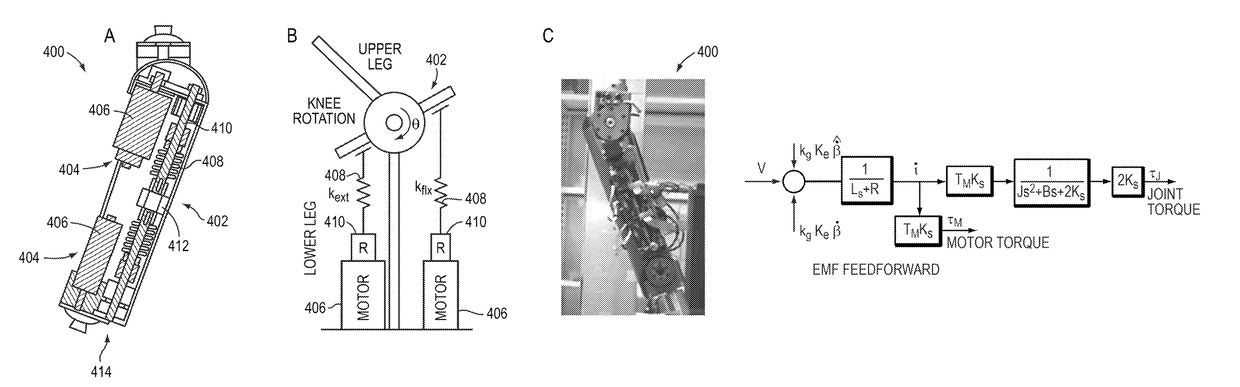
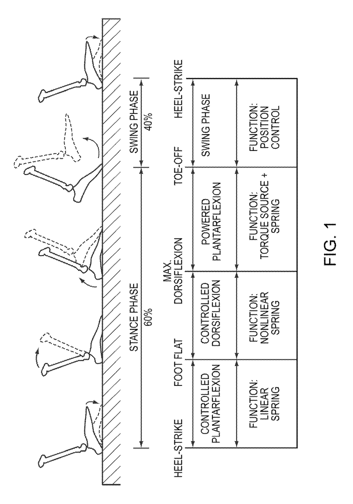
[0008]Lower-extremity augmentation may rely on a muscle-tendon architecture employing series-elasticity as a means of amplifying available joint power, reducing motor work, and improving shock tolerance. An intact ankle-foot for instance employs a series-elastic actuator in the form of the calf muscle (motor) driving through the Achilles tendon (series-elasticity). A model of an intact human ankle progressing through various phases of a gait cycle is depicted in FIG. 1. Elastic energy is stored in the tendon in the controlled dorsiflexion phase and released later, like a catapult, in powered plantar flexion to augment the power applied by the calf muscle. A series elastic actuator (SEA) as described herein can provide a biomimetic response, and may be capable of amplifying power by greater than a factor of two.
[0009]A transfemoral prosthesis may include the SEA, motor technology, neuromuscular-inspired actuator control, and intrinsic inertial sensing to provide quiet and efficient biomimetic mechanical behaviors across distinct walking speeds and terrains and the transitions between these ground surfaces. The prosthesis can provide the amputee with an enhanced metabolic economy when using a powered, ankle-foot prosthesis compared to the metabolic cost when using a conventional passive-elastic prosthesis, including a normalization of self-selected walking speed and improvement in metabolic cost-of-transport across a broad walking speed range (0.75-1.75 m / sec) using sensing, control and muscle-tendon unit (MTU) actuators.
[0010]The prosthesis may integrate an artificial MTU that employs a high-torque, transverse-flux motor that reduces, in some instances over an order of magnitude, the normalized motor copper loss,
Problems solved by technology
Such passive leg systems tend not to be biomimetic; instead they tend to be passive-elastic during stance and can neither perform net non-conservative work to propel the amputee upward and forward nor deliver the temporal torque response supplied by an intact knee and ankle joint during the gait cycle, and hence fail to fully restore function when integrated onto the residual limb.
These limitations in both ankle-foot and knee designs contribute to the severity of clinical problems experienced by transfemoral amputees.
Current leg prostheses tend not to provide the balance desired by the transfemoral community.
This may be at least partially due because most ankle-foot prostheses fail to actively control a zero-moment point (ZMP) at the foot-ground interface, a balancing strategy sometimes employed in the field of humanoid robotics.
In addition to balance problems, amputees tend to tire easier and walk slower than non-amputees.
Integration of non-biomimetic ankle-foot and microprocessor-controlled knee prostheses has confounded researchers.
Although some improvements in gait have been observed with variable-damper knee designs, many problems still remain for transfemoral amputees.
For example, a variable-damper knee combined with a passive-elastic ankle-foot prosthesis offers little to no improvement in gait metabolism and walking speed compared to a mechanically-passive transfemoral system.
Although some powered knee systems have been developed, these tend not to be biomechanically-conceived, and can take hours to fit and tune to a specific wearer.
These powered knees tend to have a noisy motor and transmission system.
Other powered robotic leg systems often exhibit three fundamental limitations: inefficient actuator design, non-biomimetic actuator control software, and poorly executed terrain-adaptation software.
The result is often a noisy transmission that dissipates battery power excessively, heating the motor windings instead of applying power to the joint.
As a result, batteries must be made larger than necessary, or else the range on a battery charge is compromised unnecessarily.
Further, motor heating can be excessive when extended periods of walking (e.g., hundreds of steps consecutively) are applied.
Even the most experienced clinicians may be unable to set up such a system.
Though certain implementations of such a control may rely on playing back a temporal response at a particular terrain state, the desired behavior can be virtually impossible to tune.
Method used
Image
Click on the blue label to locate the original text in one second.
Reading with bidirectional positioning of images and text.
Examples
Embodiment Construction
[0045]Devices for transfemoral amputees typically include at least a foot-ankle device and a knee device. The foot-ankle and knee devices described herein may be used together or separately, particularly only a foot-ankle device for below-knee amputees. While the embodiments described relate to prostheses, the concepts contained herein may also be useful in other applications, including orthoses and exoskeletons.
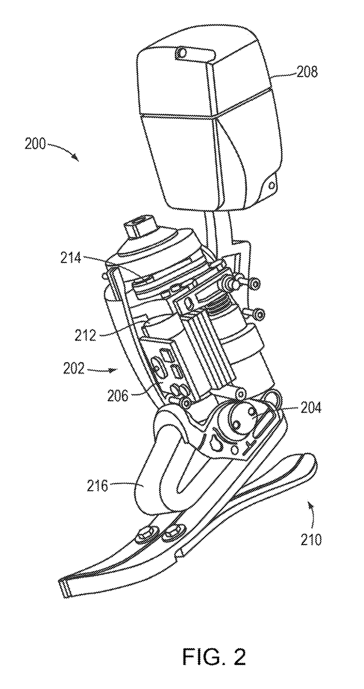
[0046]One ankle device 200 capable of restoring ankle function as defined by objective metabolic and biomechanical measures is depicted in FIG. 2. The ankle device 200 is capable of varying ankle impedance during the early to mid-stance periods of walking, emulating the quasi-static stiffness of an intact biological ankle. In addition, the prosthesis 200 provides a sufficiently large instantaneous power output and torque to propel an amputee upward and forward during powered plantar flexion, while still matching the size and weight of an intact ankle-foot complex, e.g., appr...
PUM
Abstract
In an artificial limb system having an actuator coupled to a joint for applying a torque characteristic thereto, a control bandwidth of a motor controller for a motor included in the actuator can be increased by augmenting a current feedback loop in the motor controller with a feed forward of estimated back electromotive force (emf) voltage associated with, the motor. Alternatively, the current loop is eliminated and replaced with a voltage loop related to joint torque. The voltage loop may also be augmented with the feed forward of estimated back emf, to improve the robustness of the motor controller.
Description
RELATED APPLICATIONS[0001]This application is a national stage filing under 35 U.S.C. §371 of international PCT application PCT / US2012 / 063395, filed on Nov. 2, 2012, which claims priority to and the benefit of U.S. Provisional Patent Application Ser. No. 61 / 554,921 filed on Nov. 2, 2011, the disclosure of which is hereby incorporated herein by reference in its entirety. The application also relates to U.S. Pat. No. 8,075,633, U.S. patent application Ser. Nos. 12 / 551,845, 12 / 552,013, 12 / 552,021, 12 / 552,028, 12 / 552,036, 12 / 872,425, 13 / 079,564, 13 / 079,571, 13 / 347,443, 13 / 349,216, 13 / 356,230, and 13 / 417,949, and U.S. Provisional Patent Application Nos. 61 / 554,921, 61 / 595,453, 61 / 658,568, 61 / 659,729, 61 / 662,104, 61 / 649,640, 61 / 659,723, 61 / 679,194, and 61 / 691,684, the disclosures of which are each hereby incorporated herein by reference in their entireties.FIELD OF THE INVENTION[0002]This invention relates generally to systems and methods for lower body locomotion, and more particularly t...
Claims
Application Information
Patent Timeline
Application Date:The date an application was filed.
Publication Date:The date a patent or application was officially published.
First Publication Date:The earliest publication date of a patent with the same application number.
Issue Date:Publication date of the patent grant document.
PCT Entry Date:The Entry date of PCT National Phase.
Estimated Expiry Date:The statutory expiry date of a patent right according to the Patent Law, and it is the longest term of protection that the patent right can achieve without the termination of the patent right due to other reasons(Term extension factor has been taken into account ).
Invalid Date:Actual expiry date is based on effective date or publication date of legal transaction data of invalid patent.

