Brake lining assembly

a technology of brake lining and assembly, which is applied in the direction of brake elements, braking members, noise/vibration control, etc., can solve the problems of difficult or difficult effort, and achieve the effect of reducing the stiffness and strengthening the braking

Active Publication Date: 2017-08-22
SAF HOLLAND GMBH
View PDF23 Cites 0 Cited by
  • Summary
  • Abstract
  • Description
  • Claims
  • Application Information

AI Technical Summary

Benefits of technology

[0011]Preferably, by means of the specific weight of the intermediate layer, a mechanical and / or acoustic damping effect is provided. Advantageously, to this end, the intermediate layer is made from a material, which has a higher specific weight than the brake lining. Preferably, thus, the natural frequency of the brake lining or of the brake lining assembly may be indirectly reduced such that a damping effect is provided. Expediently, at least in a certain area, the intermediate layer is made from a material having a progressive spring characteristic. Advantageously, in order to achieve the progressive spring characteristic, various materials, preferably two different materials, are used for manufacturing the intermediate layer, wherein one material is more rigid than the other one.
[0014]Advantageously, the stiffness of the intermediate layer varies along the circumferential direction, such that the application or contact of the brake lining on a brake drum may be influenced. During the brake operation the brake drum, which rotates in the circumferential direction, exerts a torque onto the brake lining, which is in contact during the brake operation. Depending on a support or mounting of the brake shoe, said torque may reinforce the braking effect during the brake operation, i.e. when the torque acts in the direction of the support or mounting of the brake shoe (cf. brake shoe of a drum brake, which runs aground, i.e. makes contact). The load on the first area of the brake lining, when seen in the circumferential direction, is particularly high. Advantageously, by means of an intermediate layer, which is made more rigid in this area, for example, than in a second area, which is behind the first area, when seen in the circumferential direction, the application of the brake lining against the brake drum may be positively influenced in that a very even application against and / or a very even wear on the brake lining and / or the brake drum is achieved. Preferably, the difference in stiffness is achieved by using materials having different stiffnesses.

Problems solved by technology

In manufacture, it is often difficult or requires much effort to form the inner contour of the brake lining and the outer contour of the brake shoe so precisely that it becomes possible for the brake lining to be arranged on the brake lining over the entire surface thereof.

Method used


Image

  • Brake lining assembly
  • Brake lining assembly
  • Brake lining assembly

Examples


Embodiment Construction

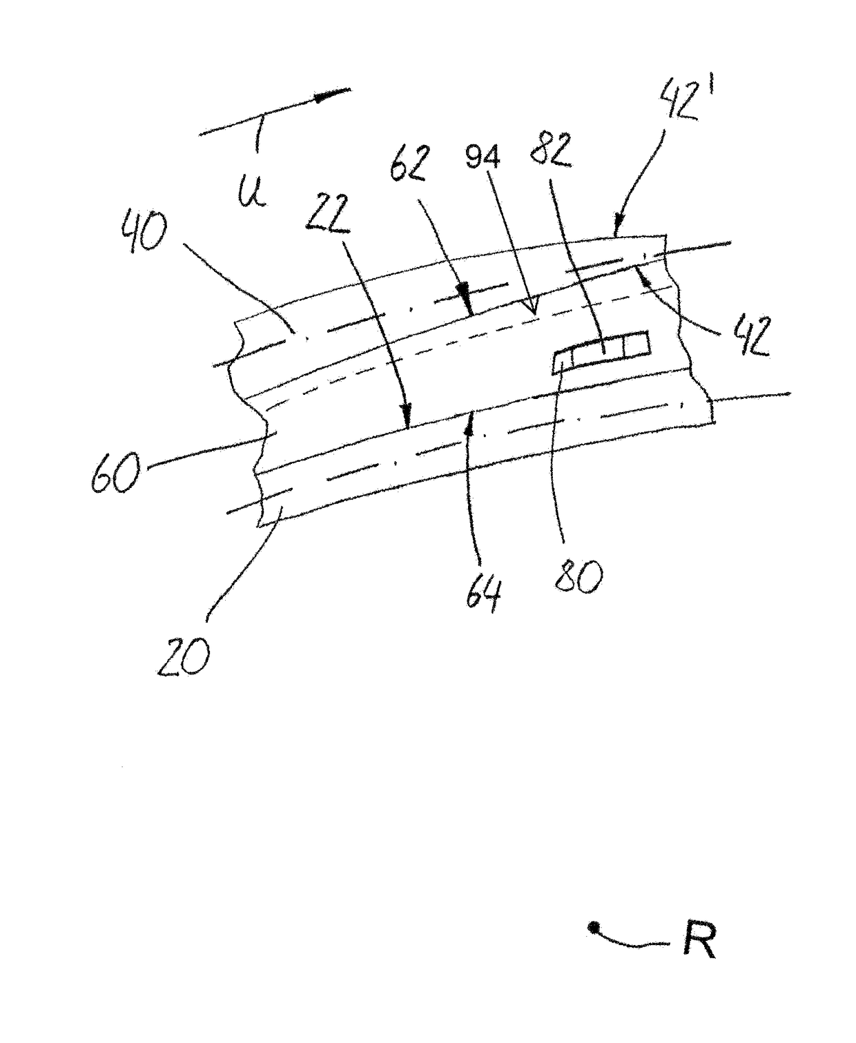
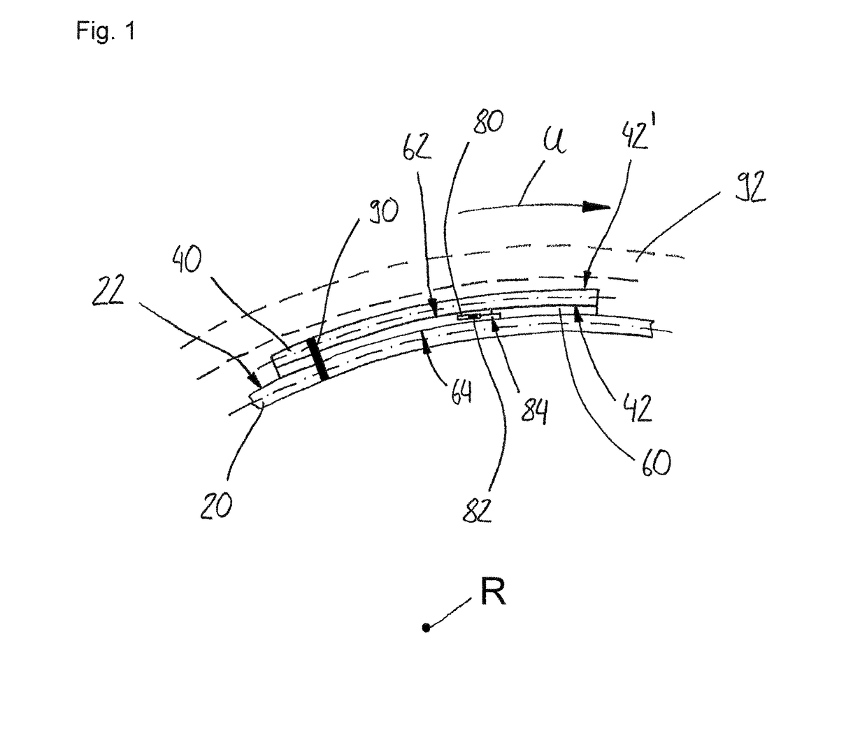
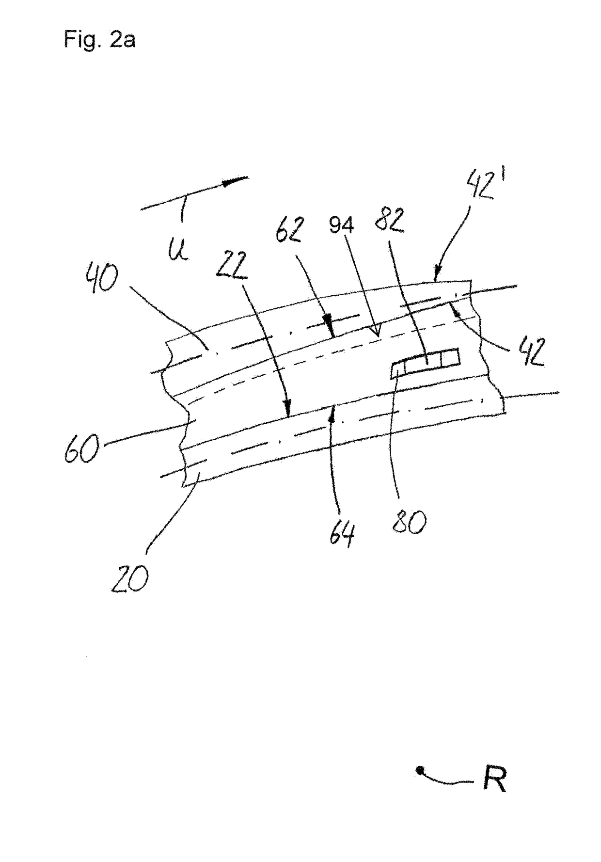
[0020]FIG. 1 shows a basic principle of a preferred embodiment of a brake lining assembly, particularly for drum brakes. A brake lining 40 is arranged on a brake shoe 20 by means of an intermediate layer 60. There is shown a circumferential direction U, along which a brake drum 92, which is indicated in dashed lines, moves or rotates. The brake lining assembly has a common axis of rotation R. The intermediate layer 60 is connected to an inner contour 42 of the brake lining 40 by means of an outer contact region, and it is connected to an outer contour 22 of the brake shoe 20 by means of an inner contact region 64. By way of example a fastener 90 is shown, which serves for connecting the brake lining 40 and the brake shoe 20 in a form-fitting and / or force-fitting manner. As a matter of course, there are provided preferably several fasteners 90. In the intermediate layer 60 an arrangement region 80 is indicated, in which an additional element 82 is arranged. The arrangement region 80 ...


PUM


Abstract

The invention relates to a brake lining assembly, particularly for drum brakes, comprising a brake shoe having an outer contour, a brake lining having an inner contour, and an intermediate layer having an outer contact region and an inner contact region. The intermediate layer is arranged between the brake shoe and the brake lining, and the intermediate layer is formed, as viewed radially with respect to an axis of rotation of the brake shoe, in such a manner that the inner contact region is matched in a form-fitting manner to the outer contour of the brake shoe in a circumferential direction of the brake shoe. The outer contact region is matched in a form-fitting manner to the inner contour of the brake lining along the circumferential direction.

Description

BACKGROUND OF THE INVENTION[0001]The present invention relates to a brake lining assembly, particularly for drum brakes, as well as an intermediate layer, particularly for being arranged between a brake lining and a brake shoe of a drum brake.[0002]In the field of commercial vehicles, drum brake linings are as a rule riveted directly onto the brake shoes, producing a direct contact between the drum brake linings (friction material) and the brake shoe(s). In order to ensure that as much of the linings as is possible has contact, very strict tolerances have to be observed (e.g. by mechanical working or by calibration), which requires great manufacturing outlay (time and costs) and which often is not possible in a process-secure manner.[0003]Therefore, the object underlying the present invention is to provide a brake lining assembly, particularly for drum brakes, as well as an intermediate layer, particularly for being arranged between a brake lining and a brake shoe of a drum brake, w...

Claims


Application Information

Patent Timeline
Patent Type & Authority Patents(United States)
IPC IPC(8): F16D65/08F16D69/04F16D65/00F16D69/00
CPCF16D65/08F16D65/0006F16D65/0012F16D69/0416F16D2069/007
Inventor DREWES, OLAFKUHR, KAI
Owner SAF HOLLAND GMBH
Why Eureka
Try Eureka