Method and system for separating fluids in a distillation tower

a technology of distillation tower and fluid separation, which is applied in the direction of rectification, condensation, lighting and heating apparatus, etc., can solve the problems of carbon dioxide concentration, difficult to separate contaminants from hydrocarbons, and contaminant corrosion, so as to reduce the concentration of carbon dioxid

Active Publication Date: 2017-08-22
EXXONMOBIL UPSTREAM RES CO
View PDF25 Cites 3 Cited by
  • Summary
  • Abstract
  • Description
  • Claims
  • Application Information

AI Technical Summary

Benefits of technology

[0016]A method for separating fluids in a distillation tower may comprise maintaining a rectifier section in the distillation tower; maintaining a controlled freeze zone section in the distillation tower that forms solids from carbon dioxide within the distillation tower; feeding a stream to the distillation tower, wherein the stream comprises the carbon dioxide; reducing a carbon dioxide concentration of the stream received by the rectifier section by: feeding a first cryogenic fluid to the controlled freeze zone section, wherein the first cryogenic fluid comprises a substantially carbon dioxide free fluid; and accumulating rectifier section stream in at least one of a holding vessel and a sump of the rectifier section; and terminating reducing the carbon dioxide concentration when the carbon dioxide concentration of the stream travelling from the controlled freeze zone section to the rectifier section is less than or equal to a maximum carbon dioxide concentration.

Problems solved by technology

Additionally, in the presence of water some contaminants can become quite corrosive.
Separating contaminants from hydrocarbons is difficult.
However, distillation of mixtures of natural gas hydrocarbons, primarily methane, and one of the most common contaminants in natural gas, carbon dioxide, can present significant difficulties.
During abnormal operations, the cryogenic distillation tower does not operate at steady-state temperature conditions.
The challenge during an abnormal operation is to get from an abnormal operation to a normal operation.

Method used


Image

  • Method and system for separating fluids in a distillation tower
  • Method and system for separating fluids in a distillation tower
  • Method and system for separating fluids in a distillation tower

Examples


Embodiment Construction

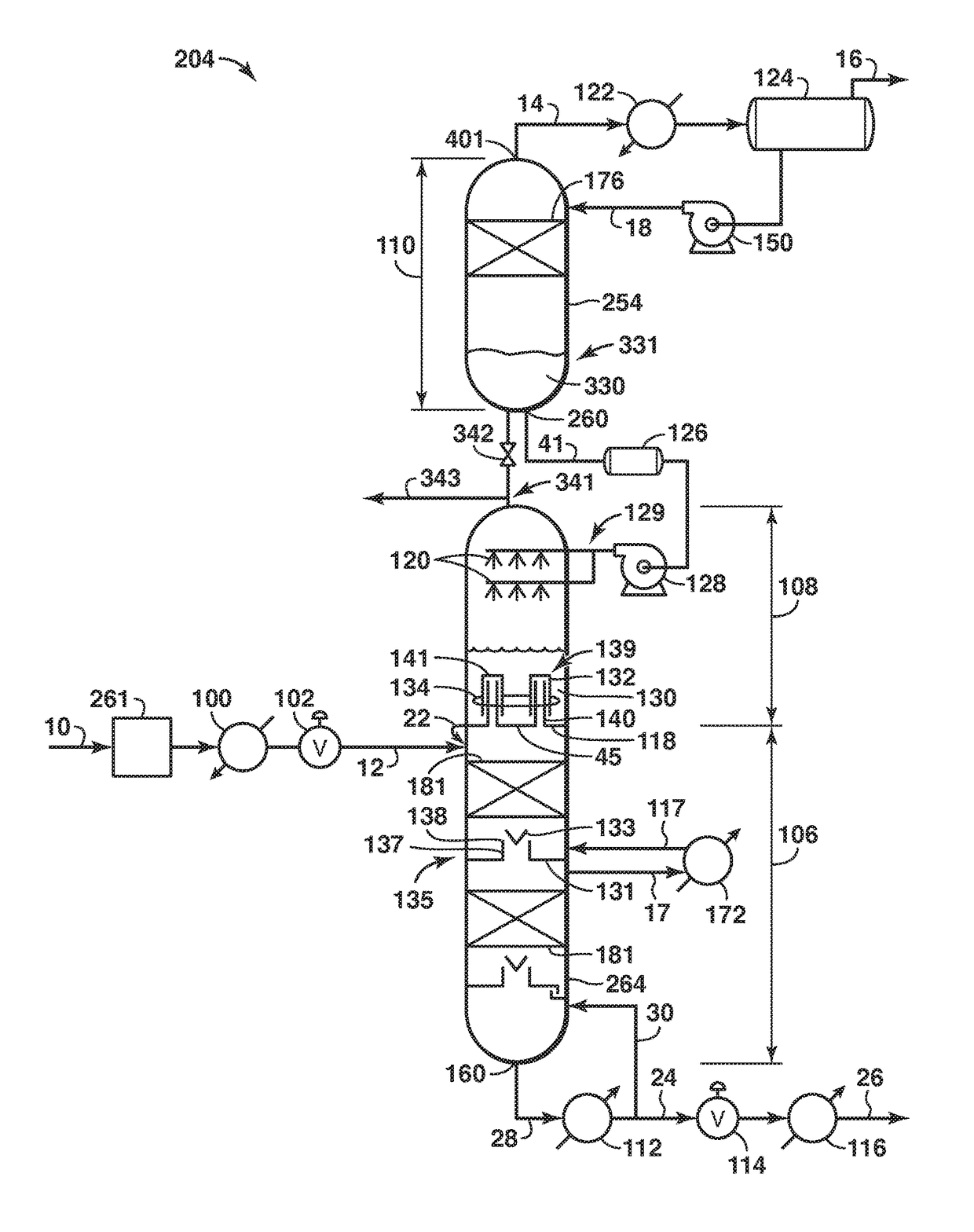
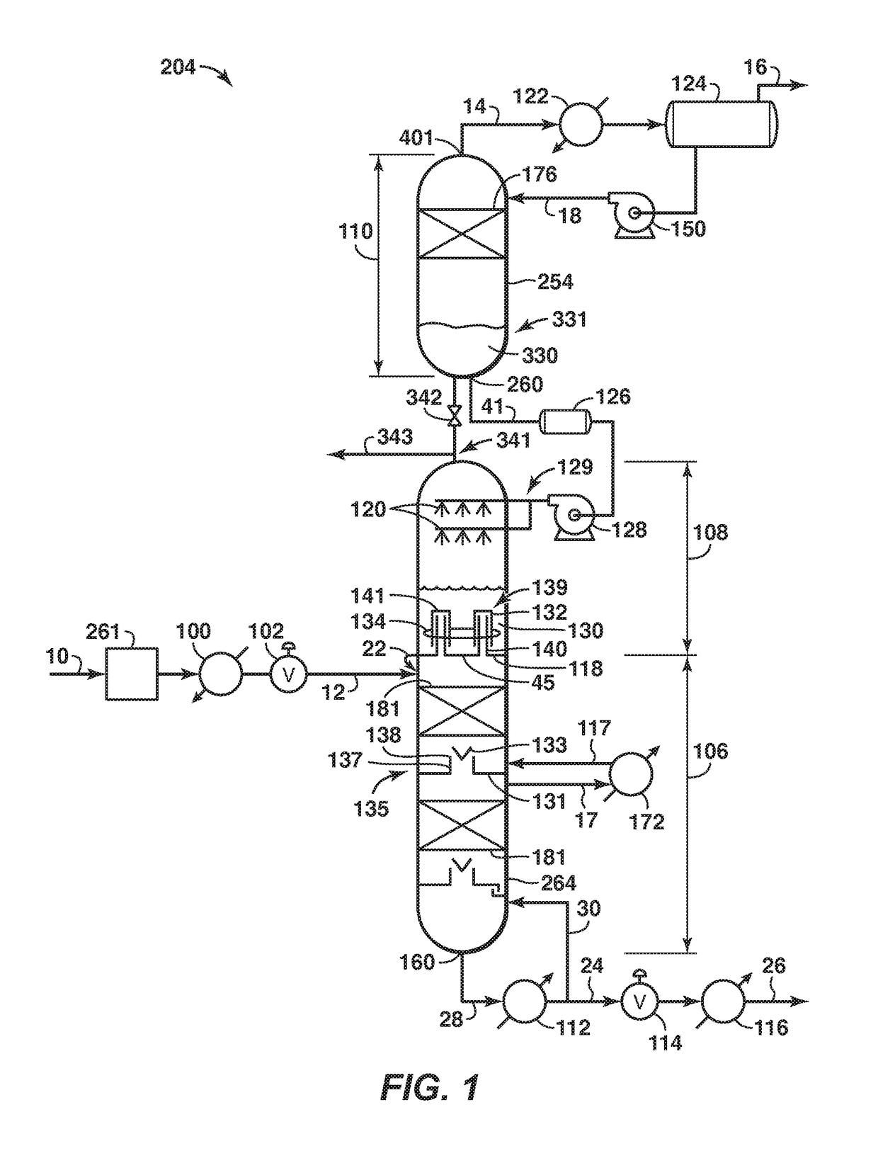
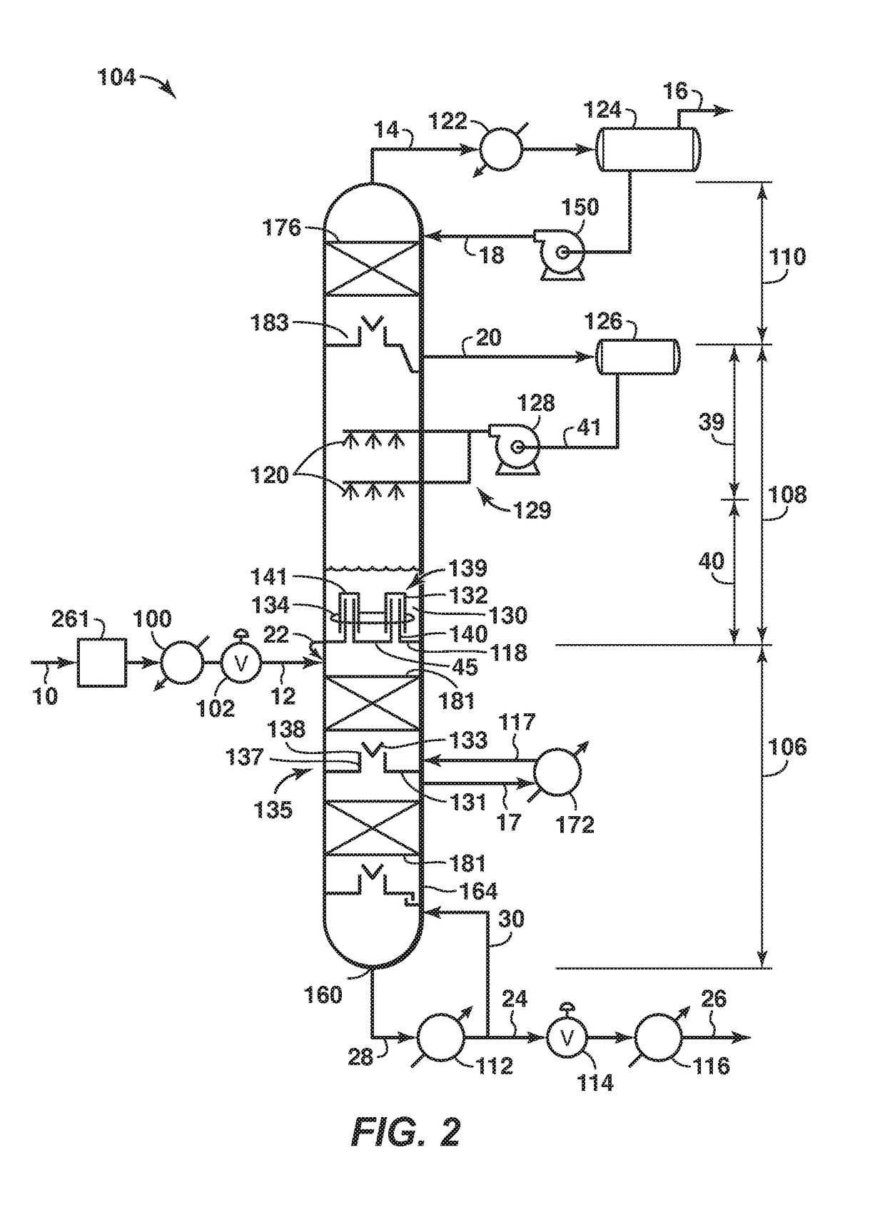
[0030]For the purpose of promoting an understanding of the principles of the disclosure, reference will now be made to the features illustrated in the drawings and specific language will be used to describe the same. It will nevertheless be understood that no limitation of the scope of the disclosure is thereby intended. Any alterations and further modifications, and any further applications of the principles of the disclosure as described herein are contemplated as would normally occur to one skilled in the art to which the disclosure relates. It will be apparent to those skilled in the relevant art that some features that are not relevant to the present disclosure may not be shown in the drawings for the sake of clarity.

[0031]At the outset, for ease of reference, certain terms used in this application and their meaning as used in this context are set forth below. To the extent a term used herein is not defined below, it should be given the broadest definition persons in the pertin...


PUM


Abstract

A method and system for separating fluids in a distillation tower. The method may include feeding a stream to the distillation tower, wherein the stream includes carbon dioxide, reducing a carbon dioxide concentration of the stream received by the rectifier section by feeding a first cryogenic fluid to the controlled freeze zone section and accumulating rectifier section stream in at least one of a holding vessel and a sump of the rectifier section, and terminating reducing the carbon dioxide concentration when the carbon dioxide concentration of the stream travelling from the controlled freeze zone section to the rectifier section is less than or equal to a maximum carbon dioxide concentration. The first cryogenic fluid may comprise a substantially carbon-dioxide-free fluid.

Description

CROSS REFERENCE TO RELATED APPLICATIONS[0001]This application claims the priority benefit of U.S. patent application No. 62 / 022,072 filed Jul. 8, 2014 entitled METHOD AND SYSTEM FOR SEPARATING FLUIDS IN A DISTILLATION TOWER, the entirety of which is incorporated by reference herein.BACKGROUND[0002]Fields of Disclosure[0003]The disclosure relates generally to the field of fluid separation. More specifically, the disclosure relates to a method and system for separating fluids in a distillation tower, such as but not limited to during start-up of a distillation tower.[0004]Description of Related Art[0005]This section is intended to introduce various aspects of the art, which may be associated with the present disclosure. This discussion is intended to provide a framework to facilitate a better understanding of particular aspects of the present disclosure. Accordingly, it should be understood that this section should be read in this light, and not necessarily as admissions of prior art....

Claims


Application Information

Patent Timeline
Patent Type & Authority Patents(United States)
IPC IPC(8): F25J3/06F25J3/02
CPCF25J3/0214F25J3/0209F25J3/0233F25J3/0266F25J3/0295F25J2200/50F25J2200/02F25J2200/30F25J2200/74F25J2205/04F25J2205/20F25J2210/62F25J2235/60F25J2245/02F25J2280/10F25J2280/40F25J2290/40F25J2290/62Y02C10/12Y02C20/40
Inventor NORTHROP, P. SCOTTVALENCIA, JAIME A.
Owner EXXONMOBIL UPSTREAM RES CO
Why Eureka
Try Eureka