Hydrogen generator and the application of the same

a generator and hydrogen technology, applied in the field of hydrogen generators, can solve the problems of low reaction rate, limited improvement effect, and degrading the commercial value of the resulting hydrogen-containing gaseous mixture, and achieve the effect of reducing co concentration

Inactive Publication Date: 2011-03-17
GREEN HYDROTEC
View PDF6 Cites 3 Cited by
  • Summary
  • Abstract
  • Description
  • Claims
  • Application Information

AI Technical Summary

Benefits of technology

[0018]a de-CO element for oxidizing CO therein into CO2 to reduce CO concentration,wherein the hydrogen generator, the heat exchanger and the de-CO element are arranged in such a way that the product of the hydrogen generator conducts heat exchange with the hydrogen-producing raw material entered into the hydrogen generation device in the heat exchanger to increase the thermal efficiency of the device, so as to preliminarily heat the hydrogen-producing raw material before being entered into the preheating zone; and after the product of the hydrogen generator exits from the heat exchanger, it is then entered into the de-CO element to remove the CO contained therein.

Problems solved by technology

If the reforming reactor per se has poor heat transfer performance, it will be impossible for heat energy at the heat source side of the reforming reactor to be transferred to the whole body of the reforming reactor, causing that a hot zone is formed near the heat source side of the reforming reactor and a cold zone is formed at regions away from the heat source.
The cold / hot zones formed due to the poor heat transfer performance will cause a low reaction rate and a low conversion extent of the methanol steam reforming reaction in the cold zone and cause H2 and CO2 generated from the reforming reaction to react into CO and H2O in the hot zone due to the over-high temperature, thereby degrading commercial value of the resulting hydrogen-containing gaseous mixture.
Through continued research efforts, the present inventors have found that simply enlarging the surface area of the catalyst bed only delivers a very limited improvement effect, and enlarging the surface area excessively may even lead to an undesirable effect.

Method used


Image

  • Hydrogen generator and the application of the same
  • Hydrogen generator and the application of the same
  • Hydrogen generator and the application of the same

Examples


example 1

Hydrogen Production Test at a Rate of 200 Liters / Hour (L / hr)

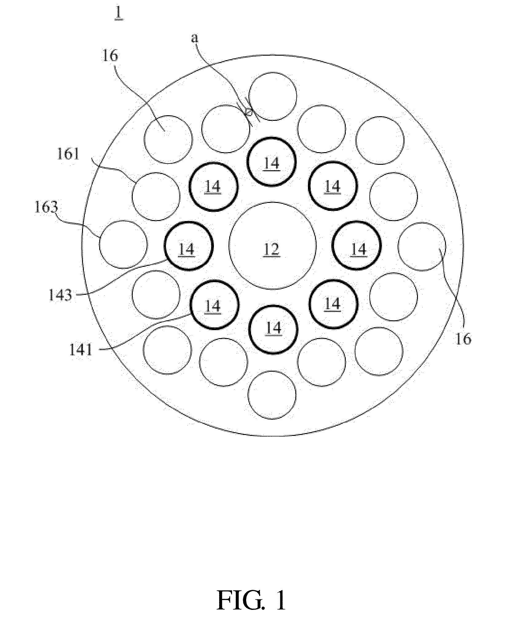
[0058]The cylindrical hydrogen generator 1 shown in FIG. 1 was used, where an aluminum alloy (Al-6061) was used as the first medium composing the hydrogen generator 1, and the hydrogen generator 1 has a diameter of about 51 mm, a depth of about 50 mm and a shortest distance a between individual channels of about 1 mm. The oxidation zone 12 located at the center of the hydrogen generator 1 has a diameter of about 13 mm and a depth of about 50 mm, and was filled with about 9 g of PBN oxidizing catalyst therein; the eight channels of the preheating zone 14 have a diameter of about 7 mm and a depth of about 50 mm; and the sixteen (16) channels of the reforming zone 16 have a diameter of about 7 mm and a depth of about 50 mm, and were filled with about 43 g of reforming catalyst JM-51 therein.

[0059]Methanol was used as the hydrogen-producing raw material, and a mixture of methanol and air was used as a fuel for the oxidizing rea...

example 2

Hydrogen Production Test at a Rate of 200 L / h

[0060]The same hydrogen generator and process as those of Example 1 were used to perform the methanol steam reforming reaction. However, brass (70% Cu, 30% Zn, with a thermal conductivity of about 121 W / m-K) was used instead as the first medium composing the hydrogen generator 1, and the supplying rate of methanol in the fuel was adjusted in such a way that hydrogen was produced at a rate of 200 L / hr. The temperature distribution of the hydrogen generator 1 was measured, thermal efficiency of hydrogen and the total methanol was calculated, and a CO content of the resulting hydrogen-containing gaseous mixture was analyzed, with the results being recorded in Table 1.

example 4

Hydrogen Production Test at a Rate of 200 L / hr

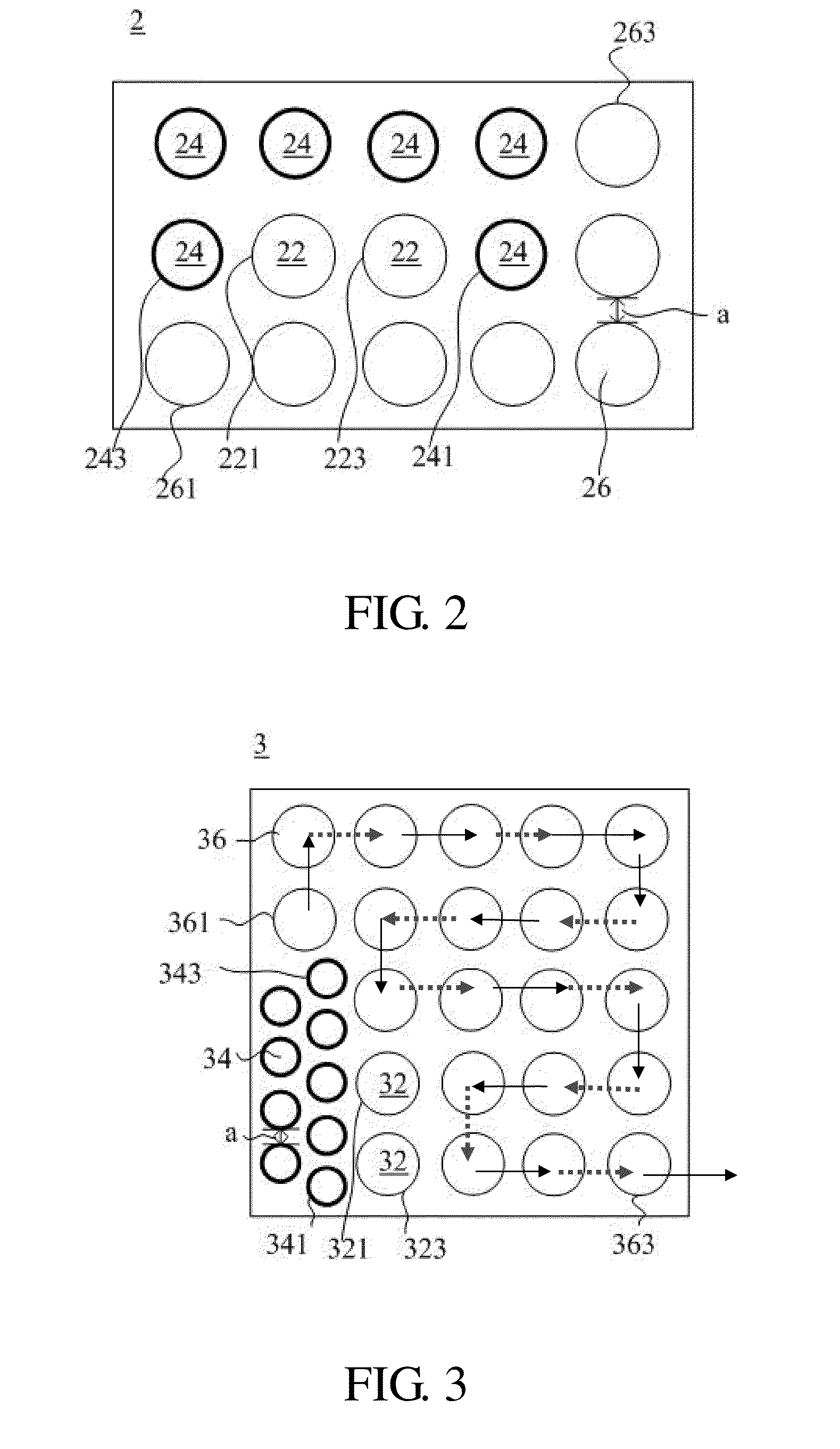
[0063]The rectangular hydrogen generator 2 shown in FIG. 2 was used, where an aluminum alloy (Al-6061) was used as the first medium composing the hydrogen generator 2. The hydrogen generator 2 has dimensions of about 55 mm×about 34 mm×about 50 mm and a shortest distance a between individual channels of about 1.5 mm. The oxidation zone 22 of the hydrogen generator 2 has a channel diameter of about 9 mm and a depth of about 50 mm, and was filled with about 4 g of PBN oxidizing catalyst therein; the preheating zone 24 has a channel diameter of about 7 mm and a depth of about 50 mm; and the reforming zone 26 has a channel diameter of about 9 mm and a depth of about 50 mm, and was filled with about 29 g of reforming catalyst JM-51 in the channels thereof.

[0064]As in Example 1, methanol and water were used as the hydrogen-producing raw materials, and a mixture of methanol with air was used as a fuel for the oxidizing reaction. Here, methanol u...


PUM


Abstract

A hydrogen generator essentially composed of a first medium is provided, comprising: a reforming zone, a preheating zone and a heat source. The reforming zone is used for containing a reforming catalyst so as to perform a steam reforming reaction of a hydrogen-producing raw material to generate hydrogen; and the heat source provides heat to the preheating zone and reforming zone, so that the hydrogen-producing raw material is firstly preheated in the preheating zone and then performs the steam reforming reaction in the reforming zone. The reforming zone and preheating zone are divided with a shortest interval of at least about 0.5 mm with the first medium, wherein the first medium has a thermal conductivity (K) of at least about 60 W / m-K.

Description

CROSS-REFERENCES TO RELATED APPLICATIONS[0001]This application claims priority to Taiwan Patent Application No. 098130886, filed on Sep. 14, 2009, the contents of which are herein incorporated by reference in its entirety.BACKGROUND OF THE INVENTION[0002]1. Field Of the Invention[0003]The present invention relates to a hydrogen generator, and more particularly, to a hydrogen generator for providing a hydrogen-containing gaseous mixture with low carbon monoxide (CO) content and the application thereof.[0004]2. Descriptions of the Related Art[0005]Hydrogen is an important fuel source for many energy conversion devices. For example, fuel cells renowned as a “green environment-friendly power generator” just use high purity hydrogen as a fuel for reacting with oxygen (or the air) to generate power by converting the chemical energy directly into the electric energy.[0006]A conventional method of producing hydrogen that is commonly used is the steam reforming reaction (SRR) in which, at th...

Claims


Application Information

Patent Timeline
Patent Type & Authority Applications(United States)
IPC IPC(8): B01J10/00B01J19/00
CPCB01J8/067C01B2203/1076B01J2208/00398B01J2208/00415B01J2208/00504B01J2208/0053B01J2219/0277B01J2219/1923C01B3/384C01B2203/0233C01B2203/066C01B2203/0811C01B2203/0833C01B2203/085C01B2203/0866C01B2203/1041C01B2203/1052C01B2203/1064C01B2203/107B01J2208/00309Y02P20/52
Inventor REI, MIN-HONCHEN, SHIH-CHUNGYANG, SHENG-YUANCHEN, YU-LINYEH, GUAN-TYNGHUNG, CHIA-YEHKAO, YU-LING
Owner GREEN HYDROTEC
Why Eureka
Try Eureka