Carbon monoxide converter

a converter and carbon monoxide technology, applied in the direction of combustible gas production, electrochemical generators, chemical/physical/physicochemical processes, etc., can solve the problems of reducing the conversion of co and a deteriorated catalyst, deteriorating the catalyst, and lowering the output, so as to reduce the concentration of co efficiently and prevent the effect of rapid reaction

Inactive Publication Date: 2005-09-08
HONDA MOTOR CO LTD
View PDF6 Cites 2 Cited by
  • Summary
  • Abstract
  • Description
  • Claims
  • Application Information

AI Technical Summary

Benefits of technology

[0007] The catalyst temperatures in the carbon monoxide converter are controlled by arranging the shift catalyst beds in tandem, thereby efficiently reducing the concentration of CO in a reformed gas. The shift catalyst beds are preferably arranged in a gas flow direction such that they are shorter on the upstream side, on which a gas containing CO and H2O is introduced, and longer on the downstream side, on which a gas containing the produced H2 and CO2 is discharged. A rapid reaction can be prevented by making the catalyst bed shorter at an upstream stage generating large heat. The deterioration of the catalyst can be prevented by controlling the temperatures of the shift catalyst beds to 330° C. or lower during the shift reaction. To achieve such precise control, a heat exchanger is preferably disposed upstream of each shift catalyst bed. The catalyst temperatures can be maintained within a predetermined range by controlling the gas temperature at the inlet of each catalyst bed using a temperature sensor disposed at the inlet.
[0008] The shift catalyst beds preferably contain a shift catalyst of Pt supported on an oxide carrier. Pt, which is highly active even at relatively low temperatures, can highly efficiently convert carbon monoxide in the reformed gas at relatively low temperatures with little influence of a reverse shift reaction (CO2+H2→CO+H2O).

Problems solved by technology

However, it is known that carbon monoxide or impurities in the hydrogen-rich gas act as poison to platinum i an anode catalyst in some low-temperature fuel cells, lowering the output.
However, an exothermic shift reaction elevates a catalyst temperature as going downstream through catalyst beds, resulting in a lowered CO conversion and a deteriorated catalyst.
However, this carbon monoxide converter fails to sufficiently control the temperature under a high load, resulting in deteriorating the catalyst.
However, this carbon monoxide converter is also disadvantageous in that the temperature is not sufficiently controlled under a high load, resulting in deteriorating the catalyst.

Method used


Image

  • Carbon monoxide converter
  • Carbon monoxide converter
  • Carbon monoxide converter

Examples


reference example 1

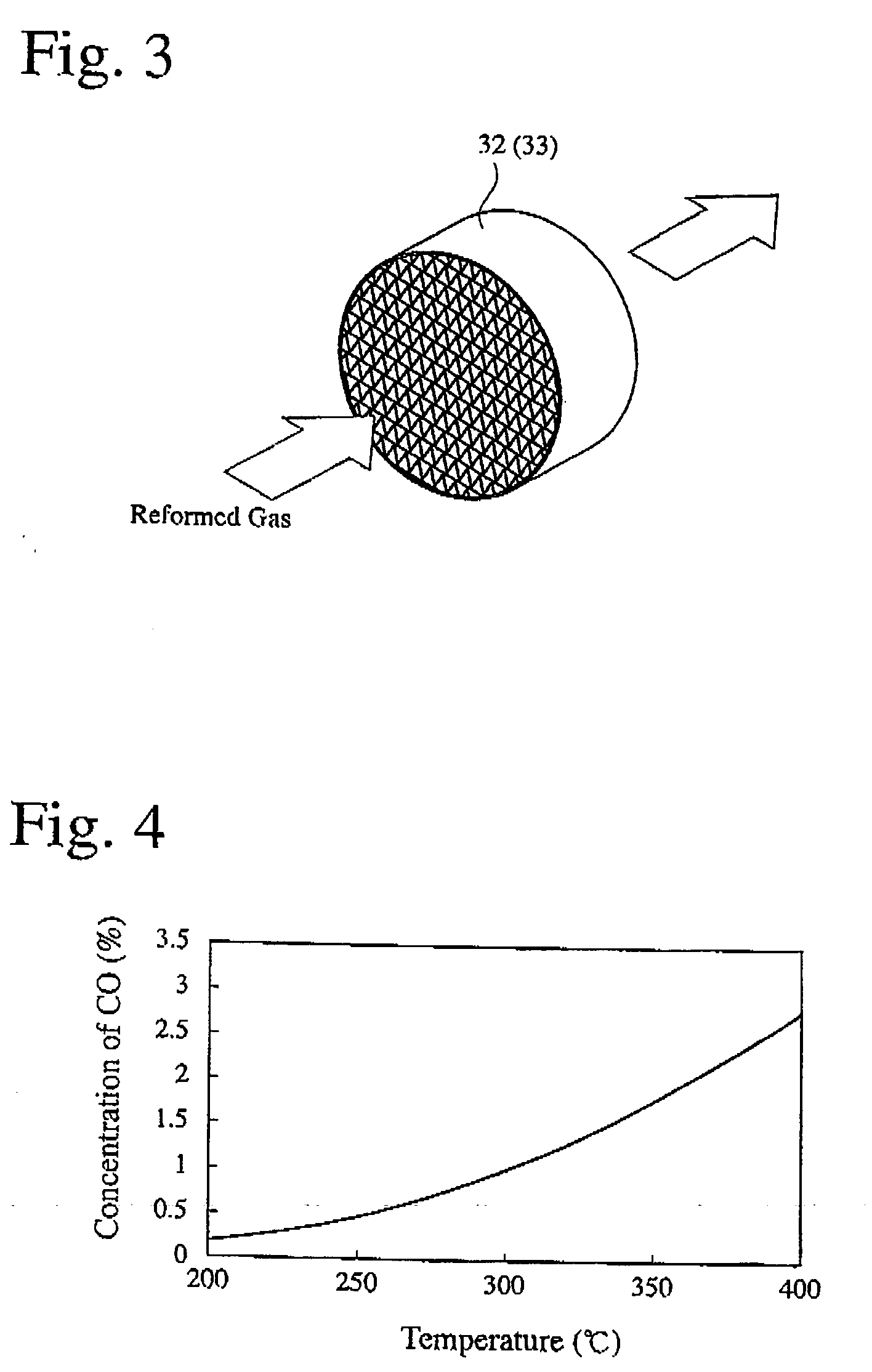
[0033] A shift catalyst layer was formed on walls of the honeycomb shown in FIG. 3 to produce a shift catalyst bed. The shift catalyst was composed of highly dispersed Pt supported on an alumina carrier. The shift catalyst bed was subjected to 100-hour durability tests at catalyst temperatures of 330° C., 380° C., and 450° C. to examine relations between the catalyst temperatures and the deterioration of performance. The results are shown in FIG. 5. Though substantially no changes were observed at the catalyst temperature of 330° C., the deterioration of performance was observed at the catalyst temperatures of 380° C. and 450° C. The transmission-electron-microscopic (TEM) observation of the shift catalysts subjected to the durability tests at 330° C., 380° C. and 450° C. indicates that Pt was more sintered at higher temperatures, causing deterioration due to the agglomeration of Pt on the carrier surface.

example 1

(1) Production of Carbon Monoxide Converter

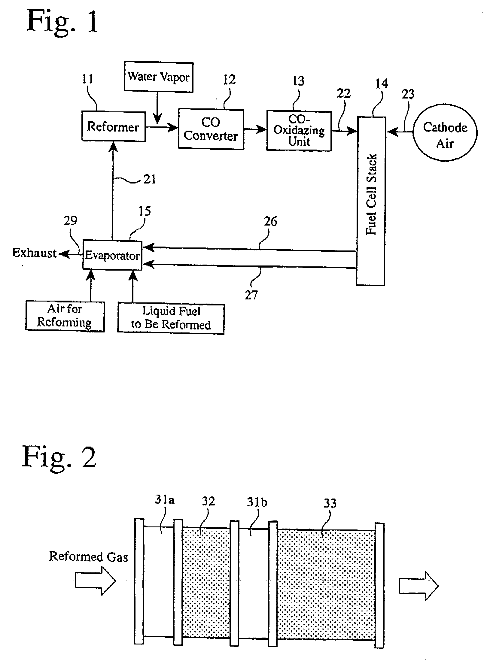
[0034]FIG. 2 shows the structure of a carbon monoxide converter used herein, which comprises a heat exchanger 3 la, a shift catalyst bed 32, a heat exchanger 31b, and a shift catalyst bed 33 in this order in a flow direction of a reformed gas. The same shift catalyst as in Reference Example 1 was used. The shift catalyst bed 32 was obtained by forming a shift catalyst layer on walls of a honeycomb of 198 mm in diameter and 30 mm in length, and the shift catalyst bed 33 was obtained by forming a shift catalyst layer on walls of a honeycomb of 198 mm in diameter and 60 mm in length. The heat exchangers 31a and 31b were coiled pipes formed in the flow path of the reformed gas. Temperature sensors (not shown) were disposed at the inlets of the shift catalyst beds 32 and 33 as well as therein, and CO concentration sensors (not shown) were disposed at the outlets of the shift catalyst beds 32 and 33. Further provided was a unit (not shown) for ...


PUM

PropertyMeasurementUnit
temperaturesaaaaaaaaaa

Abstract

There is provided a less expensive carbon monoxide converter whose catalyst temperatures can be precisely controlled even under a high load, with excellent catalyst durability. The carbon monoxide converter comprises shift catalyst beds arranged in tandem for conducting a shift reaction for converting CO and H2O to H2 and CO2.

Description

FIELD OF THE INVENTION [0001] The present invention relates to a carbon monoxide converter for efficiently converting carbon monoxide to hydrogen by a shift reaction, particularly to a carbon monoxide converter for efficiently converting carbon monoxide in a reformed gas for a fuel cell. BACKGROUND OF THE INVENTION [0002] Solid polymer electrolyte fuel cells are attracting much attention as low-pollution power sources not only for stationary applications but also for vehicle applications. The fuel cells utilize a compressed hydrogen gas, a high-purity hydrogen gas supplied from a liquid hydrogen tank, or a hydrogen-rich gas prepared by reforming an alcohol such as methanol or a hydrocarbon such as gasoline using a reformer. However, it is known that carbon monoxide or impurities in the hydrogen-rich gas act as poison to platinum i an anode catalyst in some low-temperature fuel cells, lowering the output. To reduce carbon monoxide in the hydrogen-rich gas, the reformed gas is subject...

Claims


Application Information

Patent Timeline
Patent Type & Authority Applications(United States)
IPC IPC(8): C01B32/50
CPCC01B3/16C01B3/48C01B31/20C01B2203/0205C01B2203/1294C01B2203/044C01B2203/047C01B2203/066C01B2203/0288C01B32/50
Inventor TAKAYAMA, MASAKOOKADA, HIKARU
Owner HONDA MOTOR CO LTD
Why Eureka
Try Eureka