

Device for improving air quality device
An air quality, air technology, applied in air conditioning systems, space heating and ventilation, heating methods, etc., can solve problems such as danger
- Summary
- Abstract
- Description
- Claims
- Application Information
AI Technical Summary
Problems solved by technology
Method used
Image

Examples
Embodiment 1
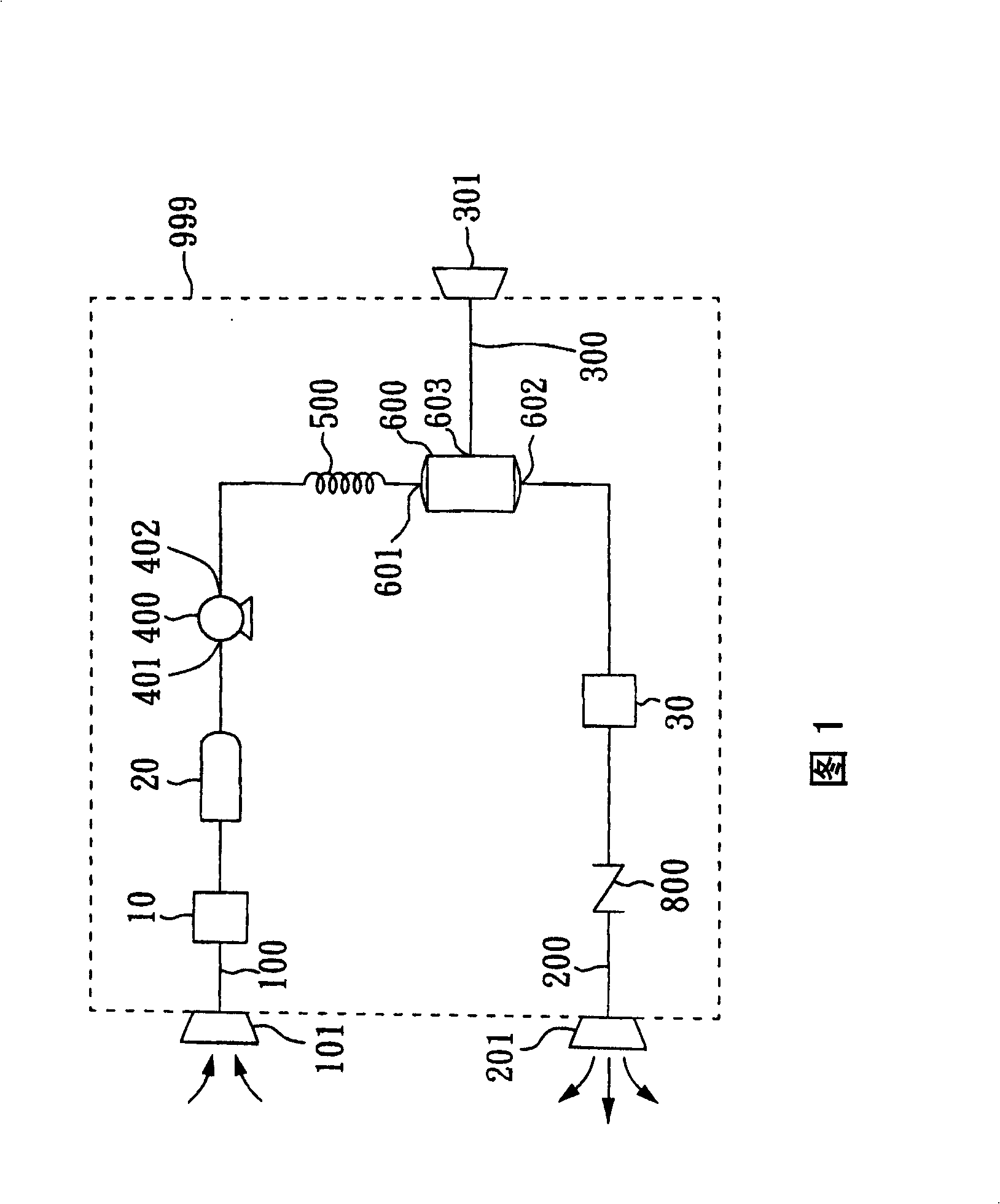
[0024] FIG. 1 is a system architecture diagram of the first embodiment of the present invention. The device includes an air suction pipe 100, a first exhaust pipe 200, a second exhaust pipe 300, an air filter 10, a muffler 20, a compressor 400, a heat exchanger 500, a gas separator module 600 , a bacteria filter 30 , and a check valve 800 . The suction port 101 of the air suction pipe is installed indoors and communicates with the indoor ambient air. The exhaust port 201 of the first exhaust pipe is also installed indoors, while the exhaust port 301 of the second exhaust pipe is installed outdoors and communicated with the outdoor ambient air.
[0025] After the compressor starts, the indoor air enters the device through the suction port 101 of the air suction pipe. Flowing through the air filter 10, the particles and impurities in the air have been removed to prevent the particles and impurities from entering the compressor and damaging the compressor. And arrange a muffle...
Embodiment 2
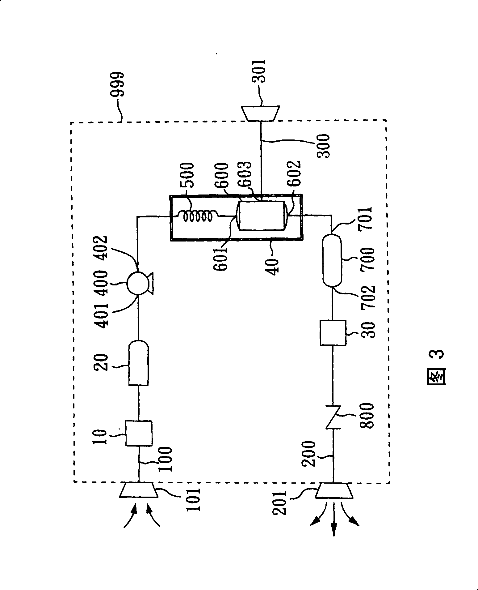
[0032] FIG. 3 is a system architecture diagram of the second embodiment of the present invention. The device includes an air suction pipe 100, a first exhaust pipe 200, a second exhaust pipe 300, an air filter 10, a muffler 20, a compressor 400, a heat exchanger 500, a gas separator module 600 , a temperature control module 40 , an air reservoir 700 , a bacterial filter 30 , and a check valve 800 . The temperature control module 40 covers the heat exchanger 500 and the gas separation module 600 . The suction port 101 of the air suction pipe is installed indoors and communicates with the indoor ambient air, and the exhaust port 201 of the first exhaust pipe is also installed indoors. The exhaust port 301 of the second exhaust pipe is installed outdoors and communicates with the outdoor ambient air.
[0033] After the compressor starts, the indoor air enters the device through the suction port 101 of the air suction pipe. Flowing through the air filter 10, the particles and i...
Embodiment 3
[0040] FIG. 4 is a system architecture diagram of a third embodiment of the present invention. The device includes an air suction pipe 100, a first exhaust pipe 200, a second exhaust pipe 300, an air filter 10, a muffler 20, a compressor 400, a heat exchanger 500, a gas separator The module 600 , a throttle valve 50 , a return gas delivery pipeline 60 , a bacterial filter 30 , and a check valve 800 . The throttle valve 50 is disposed at the first outlet 602 of the gas separation module. The return gas pipeline 60 is connected to the throttle valve 50 and the compressor inlet 401 . The suction port 101 of the air suction pipe is installed indoors and communicates with the indoor ambient air, and the exhaust port 201 of the first exhaust pipe is also installed indoors. The exhaust port 301 of the second exhaust pipe is installed outdoors and communicates with the outdoor ambient air.
[0041] After the compressor starts, the indoor air enters the device through the suction po...
PUM
 Abstract
Description
Claims
Application Information