Asymmetric coil support

a coil support and asymmetric technology, applied in the direction of conveying, transportation and packaging, etc., can solve the problems that the coil support described here does not yet fully achieve the desired

Active Publication Date: 2017-08-29
SMS LOGISTIKSYST
View PDF9 Cites 0 Cited by
  • Summary
  • Abstract
  • Description
  • Claims
  • Application Information

AI Technical Summary

Benefits of technology

[0011]According to the invention, at least the coil support elements are positioned asymmetrically to a vertical plane through a center of rotation of the coil, thereby guaranteeing resting of the coil on the coil support, with the coil support elements at different spacings from the [vertical plane through the] center of the coil resting on them. As a result, it furthermore follows that one of the coil support elements is subjected to a greater load caused by displacement of the coil center of gravity toward a coil support element than in the case of symmetrical positioning, so that this greater load can press the band end more strongly against the coil. As a result, a thicker band or a more high-strength material or the two in combination can be supported or also transported, at the same coil diameter, than is the case with comparable, symmetrically configured coil supports.
[0012]In a preferred embodiment of the apparatus according to the invention, both the coil support elements and the support prongs are positioned asymmetrically to the vertical plane through the center of rotation of the coil. This ensures that the effects described above are achieved even when the coil is lifted off the coil lifter and lies exclusively on the support prongs of the coil-lifting carriage. The apparatus according to the invention can thereby carry ultra-high-strength steel grades having a small coil diameter securely and without lift-off when the coils are moved, because the free band end is pressed against the coil with a greater force than in the case of conventional coil-lifting carriages, even when lifted. Furthermore, this guarantees that when the coil is moved, the displacement of the vertical plane of the coil is restricted to a minimum or avoided entirely.

Problems solved by technology

In practice, however, it has been shown that the coil supports described here do not yet completely achieve the desired effects in the case of coils composed of ultra-high-strength steel grades and having a small coil diameter.

Method used


Image

  • Asymmetric coil support
  • Asymmetric coil support
  • Asymmetric coil support

Examples


Embodiment Construction

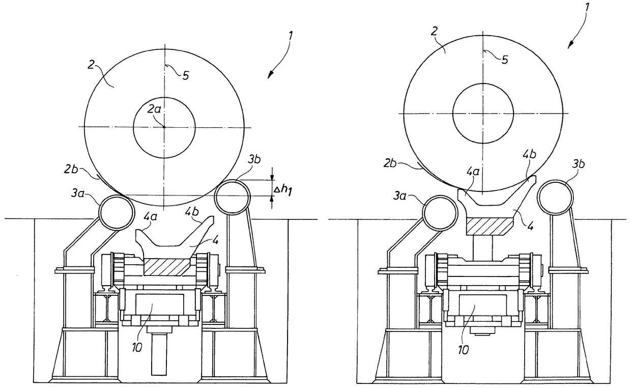
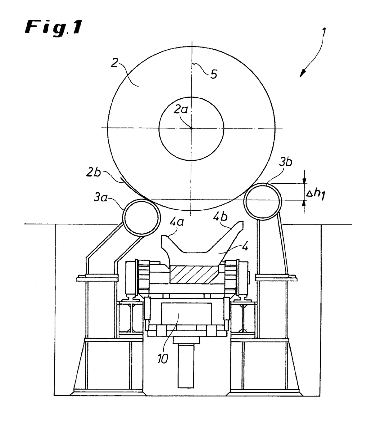
[0024]FIG. 1 shows a view of an apparatus 1 according to the invention for moving a coil 2. In the rest position shown here, the coil 2 sits on two coil support elements 3a and 3b with the coil support element 3b facing away from the band end 2b vertically offset from the coil support element 3a facing the band end 2b by an amount Δh1. As a result, the coil 2 rests on the coil support elements 3a and 3b in such a manner that the coil support elements 3a and 3b are positioned asymmetrically to a vertical plane 5 that passes through a center of rotation 2a of the coil 2. In the rest position shown here, a coil-lifting carriage 4 with two support prongs 4a and 4b and moveable upward and downward by a lifting cylinder 10 is lowered.

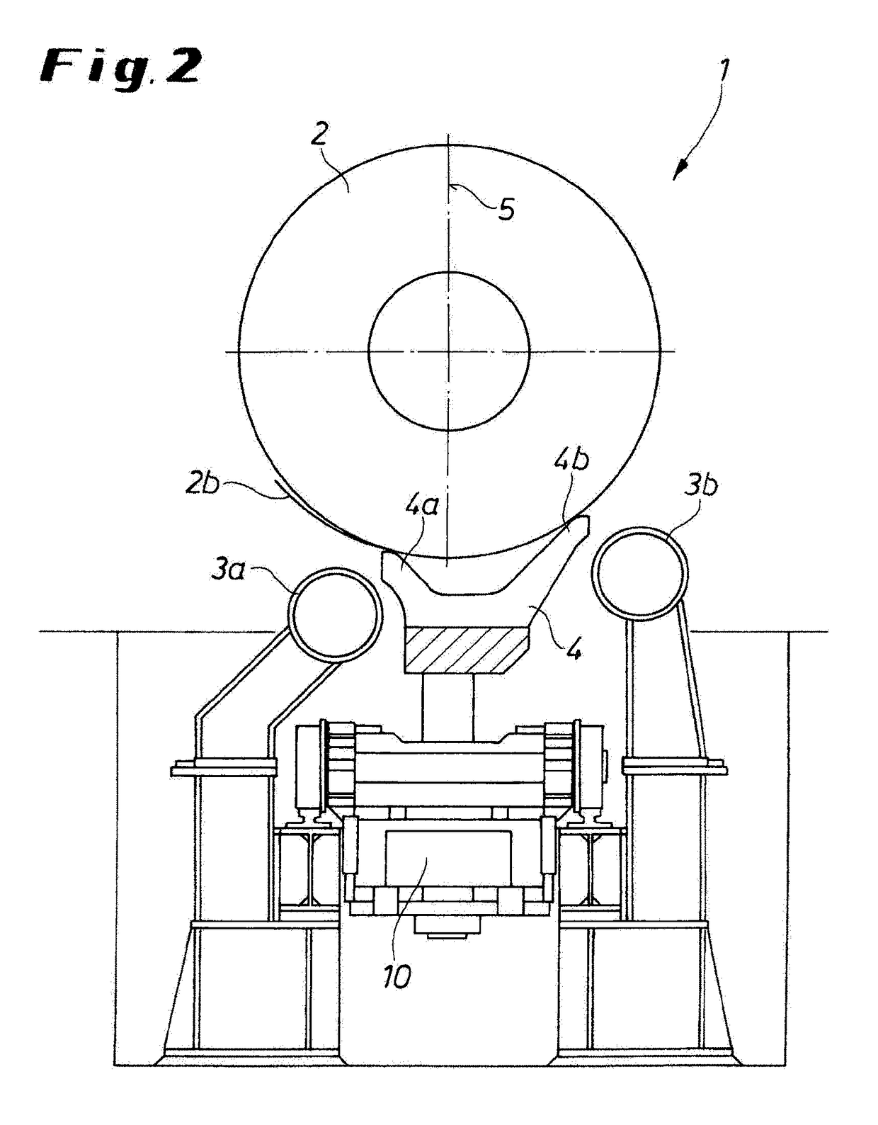
[0025]FIG. 2 shows the apparatus 1 in a moving position, in which the coil 2 no longer rests on the coil support elements 3a and 3b but rather on the support prongs 4a and 4b of the coil-lifting carriage 4 after activation of the lifting cylinder 10. Similar ...


PUM

PropertyMeasurementUnit
thicknessesaaaaaaaaaa
strengthaaaaaaaaaa
temperatureaaaaaaaaaa

Abstract

The invention relates to a device (1) in conveying equipment for moving metal strips wound to form coils (2), in particular produced from high-strength or ultra-high-strength steel grades, wherein for transport the coils (2) can be lifted and lowered from a resting position on a coil support (3) by means of a vertically adjustable coil lifting device (4), wherein the coil support (3) has two coil support elements (3a, 3b) which are laterally spaced apart from one another and the coil lifting device (4) has two support prongs (4a, 4b), characterized in that at least the coil support elements (3a, 3b) are disposed asymmetrically with respect to the vertical (5) through the center of rotation (2a) of the coil (2).

Description

CROSS REFERENCE TO RELATED APPLICATIONS[0001]This application is the US-national stage of PCT application PCT / EP2013 / 000153 filed 18 Jan. 2013.FIELD OF THE INVENTION[0002]The invention relates to an apparatus in conveying equipment for moving a metal strip wound to form a coil, in particular produced from high-strength or ultra-high-strength steel grades, wherein for transport the coil can be lifted and lowered from a rest position on a coil support by a vertically adjustable coil lifter, the coil support has two coil support elements that are laterally spaced apart from one another, and the coil lifter has two support prongs.STATE OF THE ART[0003]In a modern rolling mill, different steel grades are processed that can be roughly divided into three basic groups. These are as follows:[0004]1. Normal, generally hot-wound construction steels that are plastically deformed during winding. A free band flap, i.e. the exposed band end, practically lies against the coil from the outside, so t...

Claims


Application Information

Patent Timeline
Patent Type & Authority Patents(United States)
IPC IPC(8): B21C47/24B65G25/02
CPCB21C47/24B65G25/02B65G2201/0232
Inventor HOFMANN, KARL ROBERT
Owner SMS LOGISTIKSYST
Why Eureka
Try Eureka