Automated teller machine with an automatically actuatable locking element for locking cash boxes received in receiving compartments in these receiving compartments

a technology of automatic actuation and locking element, which is applied in the direction of atm details, furniture parts, instruments, etc., can solve the problems of complex structure of locking mechanism, high cost, and difficulty in handling, and achieve the effect of simple and compact structur

Active Publication Date: 2017-08-29
DIEBOLD NIXDORF SYST GMBH
View PDF8 Cites 0 Cited by
  • Summary
  • Abstract
  • Description
  • Claims
  • Application Information

AI Technical Summary

Benefits of technology

[0012]Since the locking and unlocking of the locking mechanism is accomplished automatically by means of the contact with the cash box when the cash box is inserted or removed, it is no longer necessary that a locking mechanism has to be locked or unlocked manually. Thus, a particularly easy handling is possible since the operator can use both hands for the insertion or removal of the cash box. In addition, elements that require a manual operation can be dispensed with so that the locking element and the entire locking mechanism can be constructed particularly easily and thus cost-efficiently. Nevertheless, by means of the automatic locking it is guaranteed that the cash box, when inserted into the receiving compartment, is always arranged in the predetermined position.
[0035]In these receiving compartments, too, in particular one, preferably two locking elements each are arranged. The locking elements may be designed and mounted identically to the afore-mentioned locking elements. As a result, it is achieved that in all receiving compartments of the automated teller machine a safe and simple locking of the cash boxes can be accomplished.

Problems solved by technology

This has the disadvantage that, when a cash box is removed, one hand is required for unlocking so that the cash box can only be handled with one hand, which makes the handling more difficult.
In addition, such locking mechanisms are complexly constructed and thus also cost-intensive.
Here, too, the locking has to be performed actively and is very complexly constructed.

Method used


Image

  • Automated teller machine with an automatically actuatable locking element for locking cash boxes received in receiving compartments in these receiving compartments
  • Automated teller machine with an automatically actuatable locking element for locking cash boxes received in receiving compartments in these receiving compartments
  • Automated teller machine with an automatically actuatable locking element for locking cash boxes received in receiving compartments in these receiving compartments

Examples


Embodiment Construction

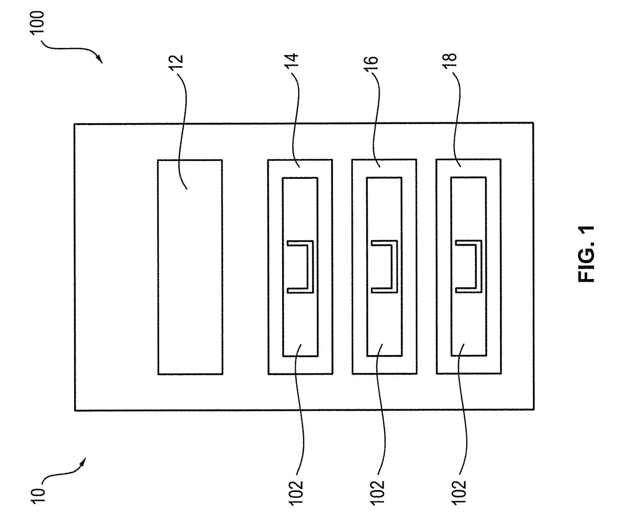
[0042]In FIG. 1, a schematic highly simplified illustration of an arrangement 100 comprised of an automated teller machine 10 and three cash boxes 102 is shown. The automated teller machine 10 has four receiving compartments 12 to 18, wherein one cash box 102 each is inserted into the receiving compartments 14 to 18 and no cash box is inserted into the receiving compartment 12.

[0043]The cash boxes 102 can be removed from the receiving compartments 12 to 18 and inserted therein. For the orderly feeding of notes of value to the cash boxes 102 and the orderly removal of notes of value from the cash boxes 102 it is necessary that these are arranged in predetermined positions within the automated teller machine.

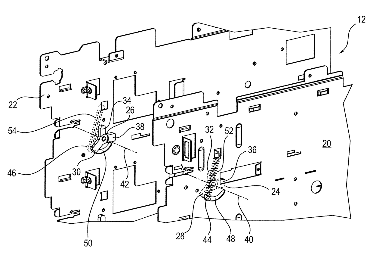
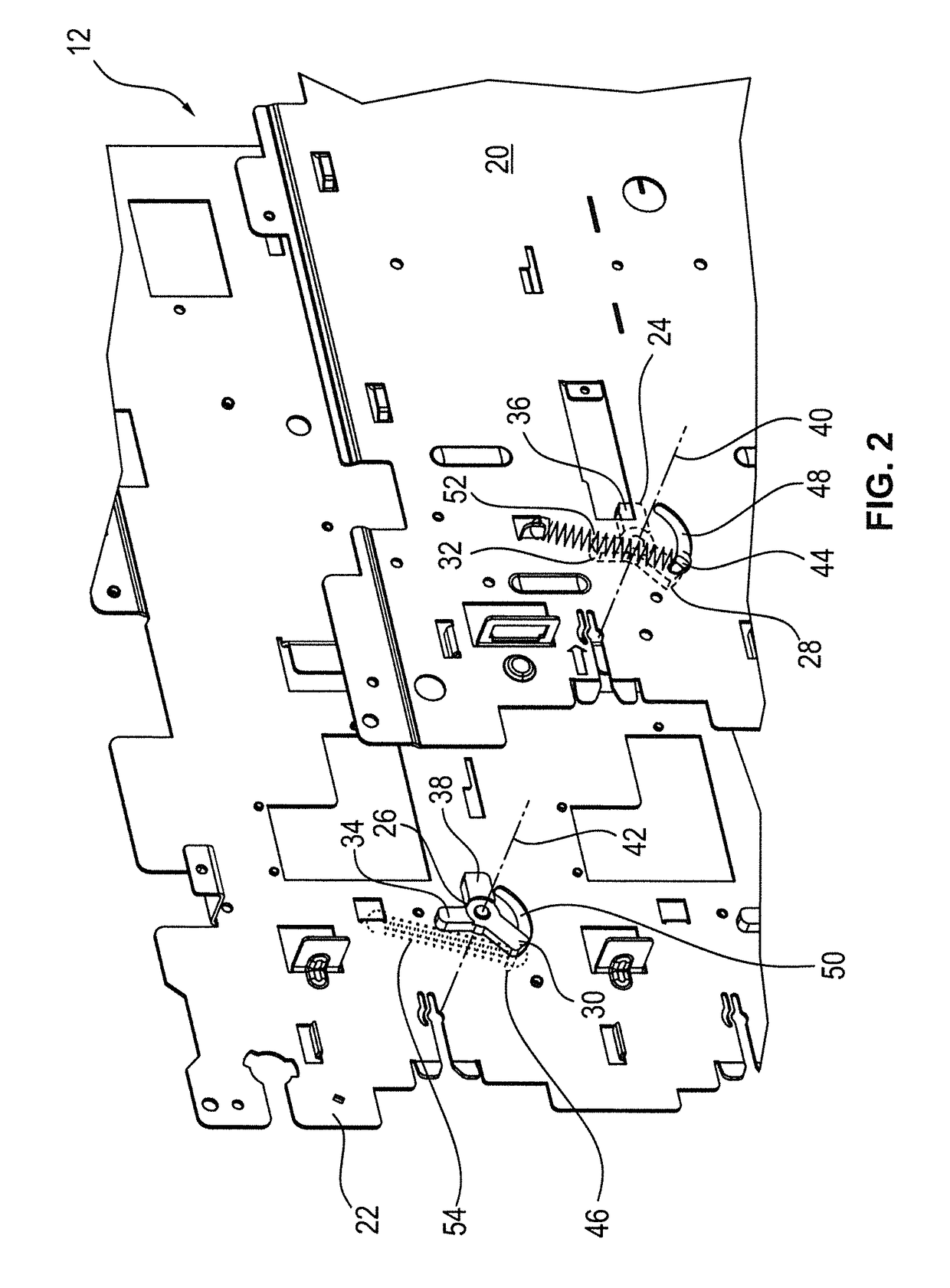
[0044]In order to guarantee this predetermined orientation, a locking mechanism described in more detail in connection with FIGS. 2 to 4 is provided in each receiving compartment 12 to 18. This locking mechanism is exemplarily described for the receiving compartment 12. The other ...


PUM


Abstract

An automated teller machine (10) has at least one receiving compartment (12 to 18) for receiving a cash box (102). At least one locking element (24, 26) is provided on a wall (20, 22) of the receiving compartment (12 to 18) and is movable between a locked and an unlocked position. The locking element (24, 26) is designed and mounted such that, when a cash box (102) is inserted the locking element (24, 26), the locking element (24, 26) is moved automatically from the unlocked into the locked position by contact with an engagement element (104) of the cash box (102).

Description

BACKGROUND[0001]1. Field of the Invention[0002]The invention relates to an automated teller machine having at least one receiving compartment for receiving a cash box.[0003]2. Description of the Related Art[0004]Known automated teller machines have several receiving compartments, into each of which a cash box can be inserted and again be removed therefrom. For the automatic feeding of notes of value to the cash box or the automatic removal of notes of value from the cash box it is necessary that the cash box is arranged in a precisely predetermined position within the receiving compartment. In order to ensure this, most automated teller machines have locking mechanisms by means of which the cash box is held in the predetermined position in the receiving compartment.[0005]In the known locking mechanisms, a locking element for locking and / or unlocking the cash box has to be actuated manually. This has the disadvantage that, when a cash box is removed, one hand is required for unlockin...

Claims


Application Information

Patent Timeline
Patent Type & Authority Patents(United States)
IPC IPC(8): G07F9/10G07D11/00E05B65/46G07F9/06A47B88/467G07F17/12G07F19/00
CPCE05B65/461A47B88/467G07D11/0006G07F9/06G07F17/12G07F19/20G07F19/205G07G1/0027G07D11/12
Inventor GO, FLORANTEHIDALGO, RONALD
Owner DIEBOLD NIXDORF SYST GMBH
Why Eureka
Try Eureka