
Transmission for a wheeled vehicle with a walking driver, and wheeled vehicle equipped with such a transmission

a technology of transmission and wheeled vehicles, which is applied in the direction of mechanical equipment, agriculture tools and machines, and gears, etc., can solve the problems of overall compactness, difficulty or indeed impossible to move the vehicle backwards, and insatiable conditions

Active Publication Date: 2017-09-12
FRANCE REDUCTEURS SA
View PDF12 Cites 10 Cited by
  • Summary
  • Abstract
  • Description
  • Claims
  • Application Information

AI Technical Summary

Benefits of technology

The present invention proposes a transmission design that allows for easy deactivation of clutch mechanisms, even in sudden stops or on grades. The design also allows for a compact overall assembly. Declutching can be done automatically or manually, and the transmission remains operable during deactivation. The use of ramps simplifies the overall assembly. The solution also includes control means for automatic actuation, which avoids any management of the clutch mechanism by the driver.

Problems solved by technology

However, such conditions are not satisfied when the vehicle stops suddenly or on a gradient.
Under such circumstances, the clutch mechanisms remain activated and it is difficult or indeed impossible to move the vehicle backwards by wheeling it over the ground.
This results in overall compactness.

Method used


Image

  • Transmission for a wheeled vehicle with a walking driver, and wheeled vehicle equipped with such a transmission
  • Transmission for a wheeled vehicle with a walking driver, and wheeled vehicle equipped with such a transmission
  • Transmission for a wheeled vehicle with a walking driver, and wheeled vehicle equipped with such a transmission

Examples


Embodiment Construction

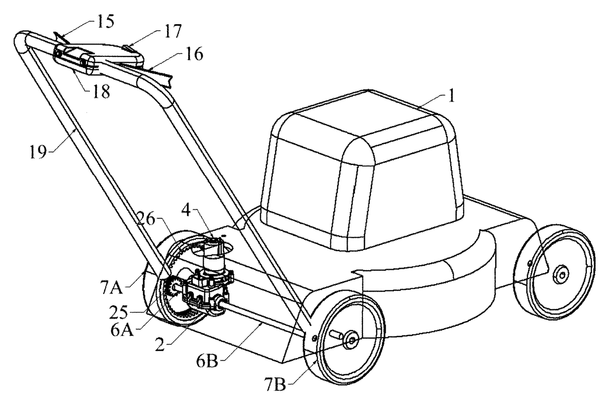
[0036]As mentioned above, the transmission of the invention is more particularly designed to be applicable to a wheeled vehicle 1, and in particular to a walk-behind wheeled vehicle.

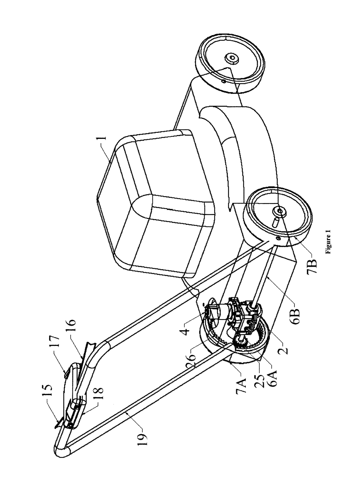
[0037]FIG. 1 shows such a transmission as applied to a lawn mower. This lawn mower has a wheeled chassis, the rear wheels of the chassis being shown at 7A, 7B in the figures.

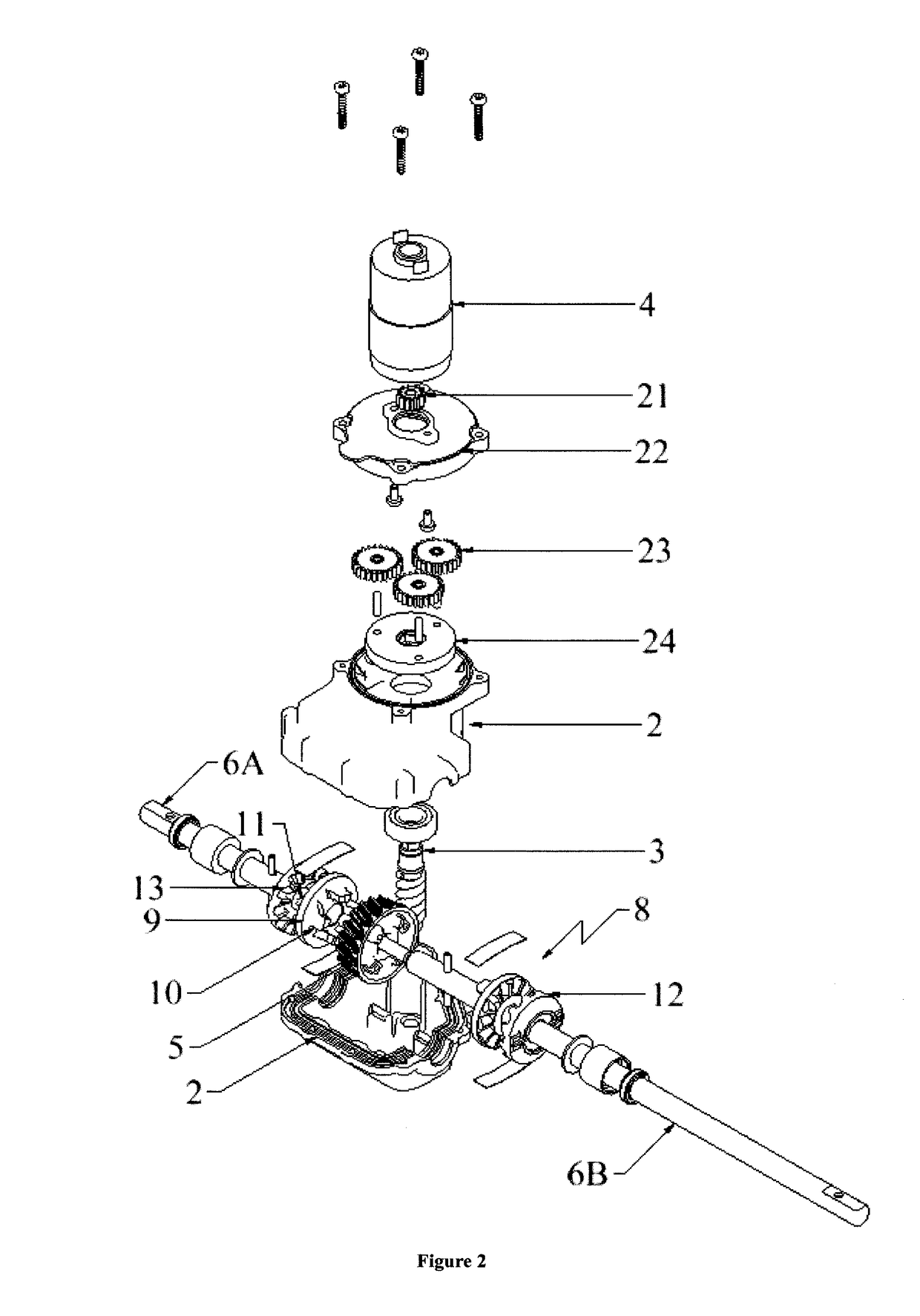
[0038]The transmission includes a fixed or stationary casing 2 carried by said wheeled chassis of the vehicle. The casing 2, which is preferably made of a synthetic material, is made up of two half-shells assembled together via a join plane. This casing 2 at least partially houses a driver member 3 formed, in this example, by an inlet shaft in the form of a worm screw. In equivalent manner, said worm screw may be replaced, in particular, by a beveled cylindrical gear.

[0039]Said driver member 3 continuously engages by meshing with a driven member 5 formed by a toothed wheel tangential to the worm screw. The driver member 3 is equipped...


PUM


Abstract

A transmission for a walk-behind wheeled vehicle, the transmission being of the type including at least one casing (2) housing a driver member (3), equipped with rotary drive motor means (4), a rotary driven member (5), two wheel drive shafts (6A, 6B) in alignment, two clutch mechanisms (8) each of which is disposed between the driven member (5) and a wheel drive shaft (6A; 6B), each clutch mechanism (8) being activated by the driven member (5) being driven in rotation forwards, and deactivatable by the wheel drive shaft (6A; 6B) with which it co-operates being driven in rotation forwards, when the speed of rotation of the wheel drive shaft (6A, 6B) is greater than the speed of rotation of the driven member (5). The rotary drive motor means (4) for driving the driver member (3) in rotation are motor means that can be controlled to rotate in two directions of rotation, and each clutch mechanism (8) is of the type that is deactivatable merely by the driven member (5) being driven in rotation in the backwards direction.

Description

RELATED APPLICATIONS[0001]This application is a National Phase Application of PCT / FR2014 / 050836, filed on Apr. 8, 2014, which in turn claims the benefit of priority from French Patent Application No. 13 53703 filed on Apr. 23, 2013, the entirety of which are incorporated herein by reference.BACKGROUND[0002]Field of the Invention[0003]The present invention relates to a transmission for a walk-behind wheeled vehicle, and the present invention also relates to a wheeled vehicle equipped with such a transmission.[0004]The invention relates more particularly to a transmission for a walk-behind wheeled vehicle, the transmission being of the type including at least one preferably non-rotary casing at least partially housing a driver member, such as an inlet shaft, equipped with rotary drive motor means, a rotary driven member, such as a toothed wheel, continuously engaging with the motor driver member, wheel drive means for driving both wheels of a single pair of wheels of the vehicle, said...

Claims


Application Information

Patent Timeline
Patent Type & Authority Patents(United States)
IPC IPC(8): F16H48/12F16D41/04F16H37/08A01D34/68A01D34/69F16H48/19F16H48/16
CPCF16H37/0813A01D34/6806A01D34/6812A01D34/69F16D41/04F16H48/19F16H48/16
Inventor BARENDRECHT, WOUTER
Owner FRANCE REDUCTEURS SA
Learn More