
Multilayer light-emitting electrochemical cell device structures

a cell device and light-emitting technology, applied in the field of new materials, can solve the problems of high encapsulation requirements, low work function cathode metals such as ca, li, cs, ba, and mg, which are commonly used in conventional approaches, and are typically unstable to oxidation or other degradation mechanisms, so as to improve performance and extend life, optimize recombination efficiency, and improve the effect of lifetime and turn-on kinetics

Inactive Publication Date: 2017-09-12
SUMITOMO CHEM CO LTD
View PDF18 Cites 0 Cited by
  • Summary
  • Abstract
  • Description
  • Claims
  • Application Information

AI Technical Summary

Benefits of technology

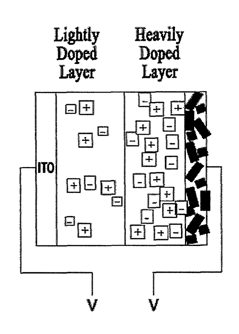
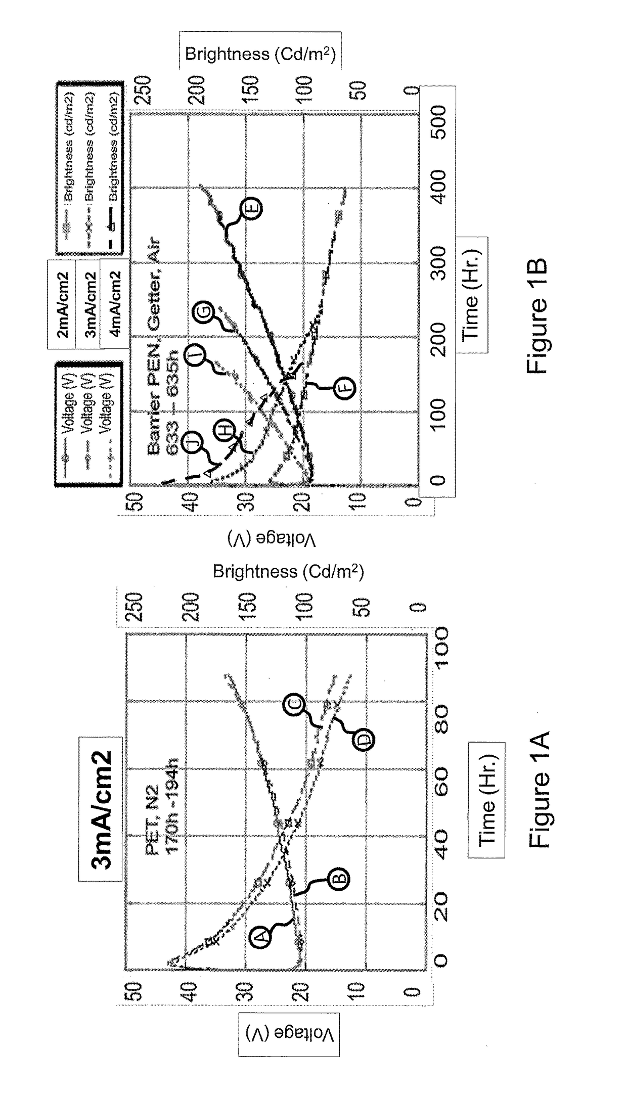
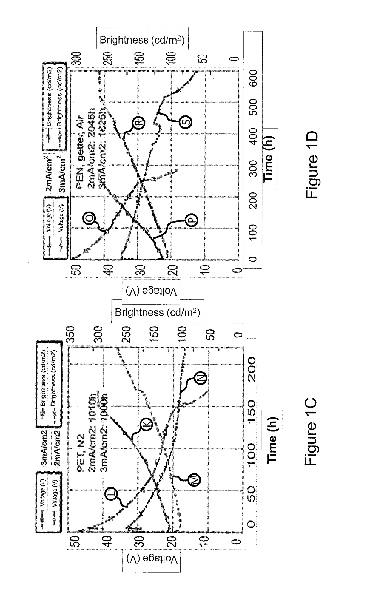
[0014]Embodiments of this invention describe novel structures and compositions for multilayer light-emitting electrochemical cell devices, particularly those adapted to work with stable and printable electrode metals, that optimize recombination efficiency, lifetime and turn-on kinetics. In particular, embodiments of the present invention provide improved performance and extended lifetime for doped electronic devices, where ionic doping levels, ionic support materials content, and electronic transport content are advantageously structured within the device.
[0015]In this invention, the doping profile of mobile or semi-mobile ionic dopants is intentionally made to be non-uniform to enhance doping in the near interface regions of a device. Special properties of the active layer of an electronic device adjacent to an electrode work to the advantage of overall efficiency and enhanced performance of the device.
[0016]In one embodiment, high doping levels in the electrode-adjacent regions lead to lower voltage charge injection at the interface and overall higher device efficiencies. In turn, these lower voltages and higher efficiencies lead to long effective device lifetimes. Of particular interest is the cathode region. Furthermore, the dopant concentration may be intentionally lower in non electrode-adjacent regions of the active layer such that dopant-related quenching is minimized and recombination efficiency is maximized. This is different from conventional OLEC approaches which assume a homogenous active layer composition prior to application of bias. This doping profile variation can optionally be associated with a variation in the light emitting and charge transporting content of the layers.
[0018]In another aspect, an electronic device is disclosed with a printed electrode and an active layer, wherein a paste to print the electrode has finite solubility of injection enhancing dopants, and, wherein, a higher concentration of dopants is present in an electrode interface region of the active layer of the device which is to be adjacent to the electrode, such that loss of dopant into the electrode paste during electrode fabrication is compensated.
[0019]In yet another aspect, an electronic device with a printed electrode and a semiconductor active layer is disclosed, wherein a film to print the electrode has finite solubility of injection enhancing dopants, and, wherein, a higher concentration of dopants is present in an electrode interface region of the semiconductor active layer of the device which is to be adjacent to the electrode, such that loss of dopant into the electrode firm during electrode fabrication is compensated.

Problems solved by technology

Low work function cathode metals such as Ca, Li, Cs, Ba, and Mg, which are commonly used in conventional approaches, including polymer OLEDs (such as devices shown in U.S. Pat. No. 5,247,190), are typically unstable to oxidation or other degradation mechanisms, particularly in the presence of moisture or oxygen.
These low work function metals also have higher encapsulation requirements and / or shorter storage lifetimes as water or oxygen leakage into the device leads to spontaneous cathode degradation.
However, high levels of doping can reduce luminance efficiency due to doping-induced quenching of luminescence.
Also, side reactions of dopants, which are exacerbated at high concentrations, can lead to accelerated degradation of device performance.
Generally speaking, it may be more difficult to inject one charge type than the other in a given active layer medium.
Often, as is the case for the combination of alkoxy substituted PPVs such as ‘Super Yellow’ (SY) as sold by Merck OLED GMBH, it is electron injection that is more difficult to achieve than hole injection, particularly when higher work function and more air stable cathodes are used.
Note that ion-motion related slow turn-on effects are a limitation in some conventional OLECs.
However, the film morphology was poor.
LEP011 used a different backbone monomer, which resulted in significantly improved print quality but poorer voltage performance.

Method used


Image

  • Multilayer light-emitting electrochemical cell device structures
  • Multilayer light-emitting electrochemical cell device structures
  • Multilayer light-emitting electrochemical cell device structures

Examples


Embodiment Construction

[0030]The present invention will now be described in detail with reference to the drawings, which are provided as illustrative examples of the invention so as to enable those skilled in the art to practice the invention. Notably, the figures and examples below are not meant to limit the scope of the present invention to a single embodiment, but other embodiments are possible by way of interchange of some or all of the described or illustrated elements. Moreover, where certain elements of the present invention can be partially or fully implemented using known components, only those portions of such known components that are necessary for an understanding of the present invention will be described, and detailed descriptions of other portions of such known components will be omitted so as not to obscure the invention. In the present specification, an embodiment showing a singular component should not be considered limiting; rather, the invention is intended to encompass other embodimen...


PUM

PropertyMeasurementUnit
thicknessesaaaaaaaaaa
thicknessaaaaaaaaaa

Abstract

Novel structures and compositions for multilayer light-emitting electrochemical cell devices are described, particularly those that are adapted to work with stable and printable electrode metals, that optimize recombination efficiency, lifetime and turn-on kinetics. In particular, embodiments of the present invention provide improved performance and extended lifetime for doped electronic devices, where ionic doping levels, ionic support materials content, and electronic transport content are advantageously structured within the device. The doping profile of mobile or semi-mobile ionic dopants is intentionally made to be non-uniform to enhance doping in the interface regions of a device where the active layer interfaces with the electrode.

Description

CROSS-REFERENCE TO RELATED APPLICATION[0001]The present application is a national stage filing under 35 U.S.C. §371 of international PCT application, PCT / US2013 / 041908, filed May 20, 2013, which claims priority to U.S. Provisional Application Ser. No. 61 / 649,076, filed May 18, 2012, the entirety of which are incorporated herein by reference.FIELD OF THE INVENTION[0002]This invention relates to novel structures and compositions for multilayer light-emitting electrochemical cell devices.BACKGROUND[0003]Several types of organic light emitting electrochemical cells (OLECs) that have homogenous active layer compositions are known in the art. OLECs provide stable, low cost organic light emitting devices requiring low operating voltage. In their typical form, OLECs, such as those described in U.S. Pat. No. 5,682,043, are deposited from a single solution containing light emitting and charge transporting conjugated polymers, for example polyphenylene vinylene polymers, polythiophene-based po...

Claims


Application Information

Patent Timeline
Patent Type & Authority Patents(United States)
IPC IPC(8): H01L51/52H01L51/50
CPCH01L51/5203H01L51/5012H01L51/5032H10K50/135H10K50/805H10K50/11
Inventor MACKENZIE, JOHN DEVINCHEN, JIAN PING
Owner SUMITOMO CHEM CO LTD
Learn More