Wireless communication system

a communication system and wireless technology, applied in the field of wireless communication systems, can solve the problems of affecting the quality of communication, so as to compensate for the degradation of communication quality

Active Publication Date: 2017-09-12
HITACHI LTD
View PDF20 Cites 3 Cited by
  • Summary
  • Abstract
  • Description
  • Claims
  • Application Information

AI Technical Summary

Benefits of technology

[0017]The receiver can detect propagation path modification from the outside using the angle information of the polarization direction transferred by electromagnetic waves from the transmitter, and compensate for degradation in quality of communication between transmission and reception by changing the polarization direction of the received electromagnetic waves when the modification is detected.

Problems solved by technology

Further, since a specific transmission path is invisible, it is difficult to specify the transmission path, and a possibility that an entire system is disabled due to blocking of the transmission path by an outsider is significantly lower as compared to a network to which wired technology is applied.
On the other hand, since the transmission path is open to outsiders, concealment of information through the transmission path and detection of an action of the outsiders tampering a specific transmission path is generally difficult as compared to the network to which the wired technology is applied.
Accordingly, there is a problem in that a vector sum of a plurality of electromagnetic waves arriving at the reception end is significantly reduced and quality of communication between transmission and reception is degraded.

Method used


Image

  • Wireless communication system
  • Wireless communication system
  • Wireless communication system

Examples


embodiment 1

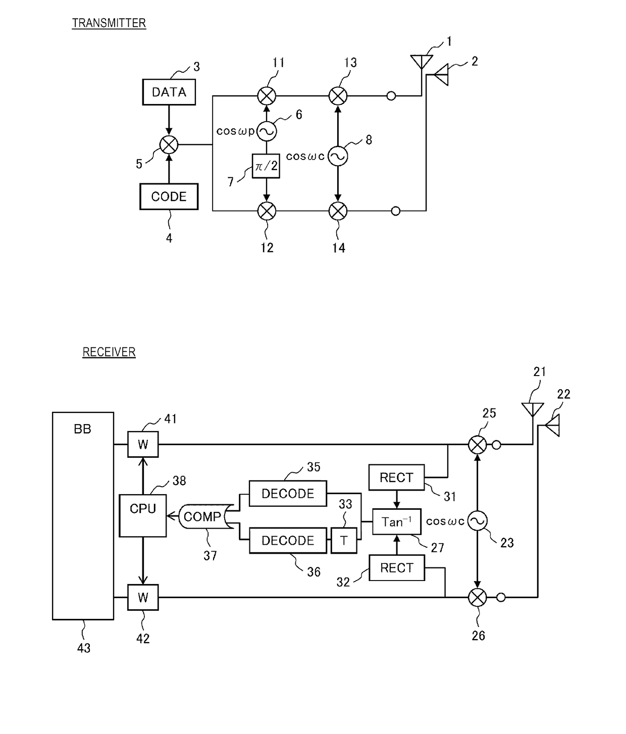
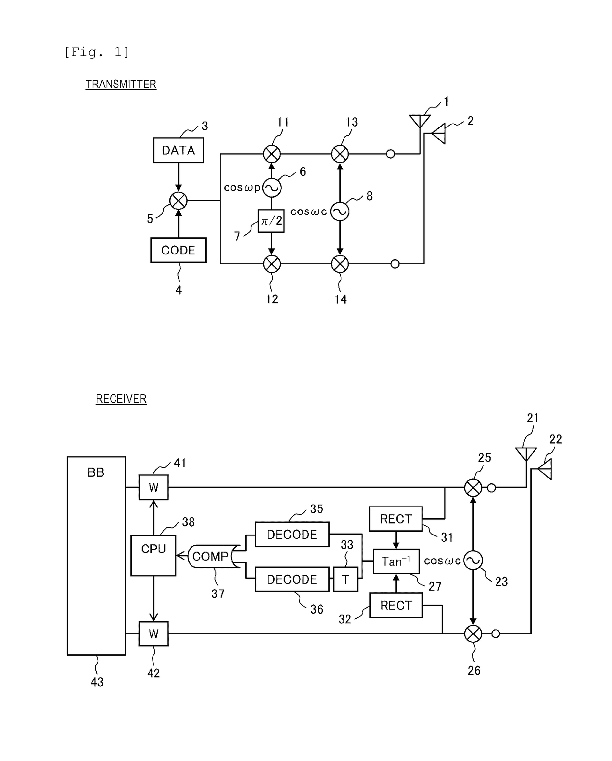
[0033]FIG. 1 illustrates a configuration diagram of a wireless communication system according to Embodiment 1 of the present invention.

[0034]A transmitter includes a digital data generation circuit (DATA) 3, and a transmission polarization angle identification code generation circuit (CODE) 4. A polarization angle identification code output from the transmission polarization angle identification code generation circuit 4 is superimposed on digital data output from the digital data generation circuit 3 by a first transmission multiplier 5, and an output thereof is branched in two. A first branch of the output of the first transmission multiplier 5 is multiplied by the output of the polarization rotation frequency generation circuit 6 by a second transmission multiplier 11, and a result thereof, that is, an output of the second transmission multiplier 11 is multiplied by an output (Frequency: ωc) of a transmission carrier frequency generation circuit 8 by a third transmission multipli...

embodiment 2

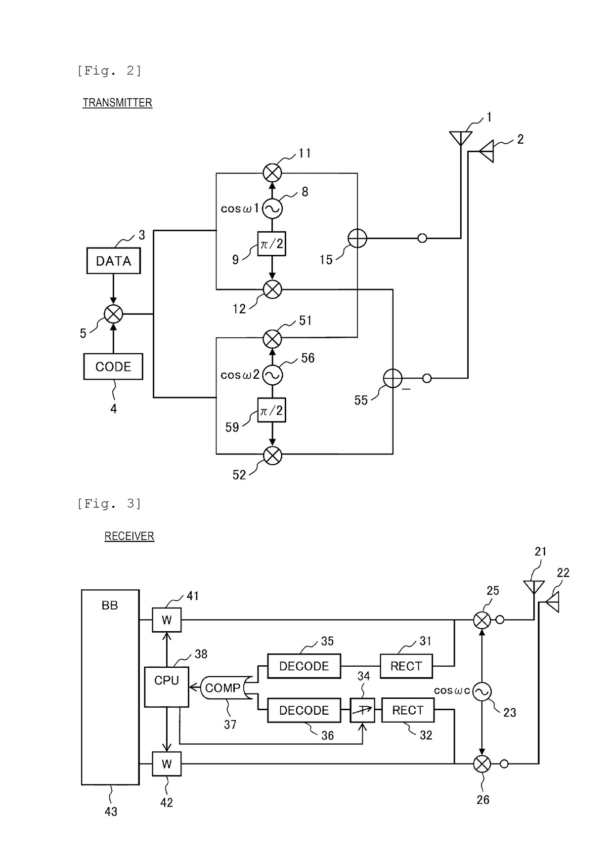
[0046]FIG. 2 illustrates a configuration diagram of a transmitter in a wireless communication system that is Embodiment 2 of the present invention. A receiver is the same as that in any one of Embodiment 1, and Embodiments 3, 5, 7, and 9 to be described below.

[0047]The transmitter includes a digital data generation circuit 3 and a transmission polarization angle identification code generation circuit 4. A polarization angle identification code output from the transmission polarization angle identification code generation circuit (CODE) 4 is superimposed on digital data output from the digital data generation circuit (DATA) 3 by a first transmission multiplier 5, and an output thereof is branched in two.

[0048]A first branch of the output of the first transmission multiplier 5 is further branched in two, one of the branches is multiplied by an output (frequency: ω1) of a first transmission carrier frequency generation circuit 8 by a second transmission multiplier 11, and a result ther...

embodiment 3

[0053]FIG. 3 illustrates a configuration diagram of a receiver in a wireless communication system that is Embodiment 3 of the present invention. A transmitter is the same as that in any one of Embodiments 1 and 2 and Embodiments 4, 6, and 8 to be described below.

[0054]The receiver includes a first reception antenna 21, and a second reception antenna 22 spatially orthogonal to the first reception antenna 21, and an output of the first reception antenna 21 is multiplied by an output (Frequency: ωc) of a reception carrier frequency generation circuit 23 by a first reception multiplier 25, a resultant signal is branched in two, a first branch is input to a first detection circuit (RECT) 31, and a second branch is input to a first weighting circuit (W) 41. An output of the second reception antenna 22 is multiplied by the output of the reception carrier frequency generation circuit 23 by a second reception multiplier 26, a resultant is branched in two, a first branch is input to a second ...


PUM


Abstract

[Object]A wireless communication system capable of detecting propagation path modification from the outside and compensating for degradation of quality of communication between transmission and reception with respect to the propagation path modification is provided. A wireless communication system includes a transmitter that transmits electromagnetic waves in which a polarization direction rotates according to a signal in which data is loaded on a carrier, and a receiver that receives the electromagnetic waves and demodulates the data, in which the transmitter imparts angle information indicating a polarization direction for transferring the data to the signal, and sets a rotation frequency of the polarization direction to a frequency lower than a frequency of the carrier, and the receiver changes a polarization direction of the received electromagnetic waves, based on the angle information transferred by the electromagnetic waves. The receiver can detect propagation path modification from the outside using the angle information of the polarization direction, and compensate for degradation in quality of communication between transmission and reception by changing the polarization direction of the received electromagnetic waves when the modification is detected.

Description

TECHNICAL FIELD[0001]The present invention relates to a wireless communication system that performs communication using a radio signal between a transmitter and a receiver.BACKGROUND ART[0002]Power plants, water purification plants, and oil refineries that are lifelines as a base of social life, and power transmission and distribution systems, water distribution systems and transportation systems associated therewith are required to be worldwide enhanced with the population growth and the improvement of a standard of living. In order to cope with such a situation, various equipment that becomes the lifeline becomes large in size, and the number of power generation equipment, water purification equipment, oil refining equipment, substation equipment, water distribution equipment, or pipelines steadily increases in individual systems or individual plant. For efficient operation of the system or the plant and ensuring of safety, a need for technology for coupling individual equipment t...

Claims


Application Information

Patent Timeline
Patent Type & Authority Patents(United States)
IPC IPC(8): H04B7/00H04L5/04H04L27/00
CPCH04B7/002H04L5/04H04L27/0002H04B10/532
Inventor TAKEI, KEN
Owner HITACHI LTD
Why Eureka
Try Eureka