Communication system

a communication system and communication technology, applied in the field of communication systems, can solve the problems of not being able to address the problems listed at the start of this document, useful triggers, etc., and achieve the effect of reducing handover failure, minimising measurement and/or related signalling

Active Publication Date: 2017-09-12
NEC CORP
View PDF15 Cites 3 Cited by
  • Summary
  • Abstract
  • Description
  • Claims
  • Application Information

AI Technical Summary

Benefits of technology

[0010]The present invention aims to provide an improved communication system and improved components of the communication system which overcome or at least alleviate one or more of the above issues. In particular, the invention aims to provide a robust handover mechanism for mobile relay nodes that reduces handover failure caused by the high speed of the MRN and by some neighbour cells not being allowed DeNB cells, whilst minimising the measurements and / or related signalling required.
[0169]The following possible solutions are considered in this document:

Problems solved by technology

Using the same method as a UE, i.e. neighbour cell measurements, may not be appropriate because:The Mobile Relay 3GPP Release 11 study item is focused specifically on the high speed train scenario, e.g. mounting RNs on train carriages.This means the MRN may be operating in a very high-speed environment where measurements are less accurateMeasurements take time to perform and any time delay may be critical in a high-speed environmentTrain-mounted MRNs use a known route.
If that neighbour cell is not an allowed DeNB cell then the event is not a useful trigger for MRN handover.
Any handover mechanism for a MRN must be robust due to the increased likelihood of handover failure (i.e. due to the high speed of the MRN and also that some neighbour cells will not be allowed DeNB cells) and the consequences of handover failure, i.e. the potentially large number of UEs that would be affected.
However, the problems listed at the start of this document are not addressed.
Additionally, this solution would require measurement gaps for the MRN to perform inter-frequency measurements.

Method used


Image

  • Communication system
  • Communication system
  • Communication system

Examples


first embodiment

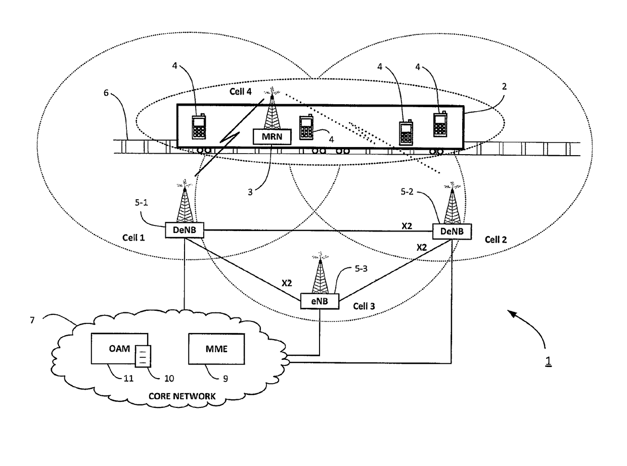
[0059]FIG. 4 shows an example timing diagram illustrating a method performed by components of the communication system 1 when configuring and performing handover related measurements and reporting, using a list 10 of allowable donor base stations. In this embodiment, the list 10 of allowed donor base stations is used by the donor base station 5-1 currently serving the mobile relay node 3. In particular, the donor base station 5-1 uses the list 10 to perform filtering of measurement reports received from the mobile relay node 3, for cells in the vicinity of the mobile relay node 3, against the allowed donor base station list, to identify those measurement reports that relate to cells of each base station 5 that is capable of providing donor services. A handover decision is then performed based on the measurement reports relating to cells of each base station 5 that is capable of providing donor services, and not measurement reports relating to cells of base stations 5 that are not ca...

second embodiment

[0065]FIG. 5 shows another example timing diagram illustrating a method performed by components of the communication system 1 when configuring and performing handover related measurements and reporting, using a list 10 of allowable donor base stations. In this embodiment, the list 10 of allowed donor base stations is obtained and used by the mobile relay node 3 rather than the donor base station 5-1. In particular, the mobile relay node 3 uses the list 10 to perform filtering of measured cells against the allowed donor base stations such that it will provide measurement reports, to the donor base station 5-1, for those cells which are operated by base stations included in the list 10 (and therefore that are capable of providing donor services) but will not provide measurement reports for those cells which are operated by base stations that are not capable of providing donor services. Accordingly, in this way the serving donor base station 5-1 does not receive measurement results for...

third embodiment

[0073]FIG. 6 shows an example timing diagram illustrating a method performed by components of the communication system 1 when configuring and performing handover related measurements and reporting, using route information.

[0074]In this embodiment, the geographical position of the mobile relay node 3 is measured and reported by taking into account information on the planned route of the mobile relay node 3 (e.g. a relay node mounted on a train which is travelling along a pre-determined route) within the area covered by the communication system 1. In this case, route information is used instead of (or in addition to) the list 10 of allowed donor base stations to discard or ignore cells that are not relevant handover candidates for the mobile relay node 3.

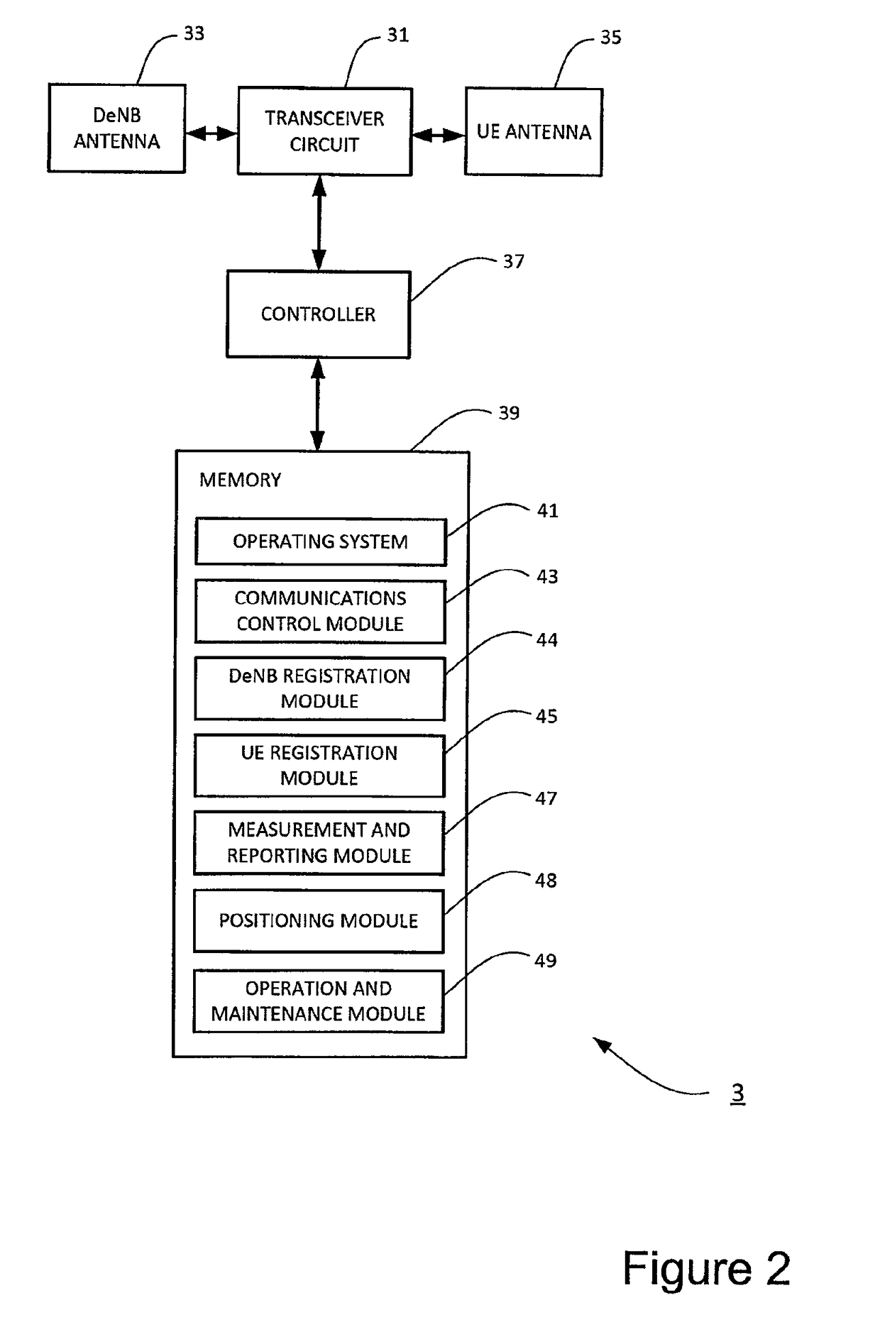
[0075]First, in step s601, the mobile relay node 3 obtains, e.g. from the OAM entity 11, and stores in its memory 39 MRN specific route information (such as geographic coordinates, list of donor base stations along the route, next all...


PUM


Abstract

A system is disclosed in which a base station initiates a handover of a mobile relay node associated with the base station. The base station obtains information that identifies at least one further base station, and that indicates that the at least one further base station is capable of providing donor services to the mobile relay node. When the base station determines that the mobile relay node requires handover, it selects, from at least one cell of the at least one further base station identified by the obtained information, a target cell for handover of the mobile relay node, and performs handover of the mobile relay node to the selected target cell.

Description

[0001]This application is a National Stage Entry of PCT / JP2013 / 068310 filed on Jun. 27, 2013, which claims priority from United Kingdom Patent Application 1212537.3 filed on Jul. 13, 2012, the contents of all of which are incorporated herein by reference, in their entirety.TECHNICAL FIELD[0002]The present invention relates to a communication system and to components thereof for providing relay services to mobile or fixed communication devices. The invention has particular, but not exclusive, relevance to handover triggers and measurements for mobile relays used in Long Term Evolution (LTE) Advanced systems as currently defined in associated 3rd Generation Partnership Project (3GPP) standards documentation.BACKGROUND ART[0003]Relaying is considered for LTE Advanced as a tool to improve, for example, the coverage of high data rates for User Equipment (UE), temporary network deployment, cell edge throughput and / or to provide coverage in new cell areas. LTE Advanced supports relaying by...

Claims


Application Information

Patent Timeline
Patent Type & Authority Patents(United States)
IPC IPC(8): H04W36/00H04B7/155H04W36/32H04W84/00
CPCH04W36/0061H04B7/155H04W36/0094H04W36/32H04W84/005
Inventor TIETZ, ROBERTPATERSON, ROBERTLEWIS, JONATHANSHARMA, VIVEK
Owner NEC CORP
Why Eureka
Try Eureka