
Method and device for efficiently irradiating a target from multiple irradiation angles in a particle therapy system

a particle therapy and target technology, applied in radiation therapy, x-ray/gamma-ray/particle irradiation therapy, therapy, etc., can solve the problems of unnecessarily long treatment sessions, manual manipulation, and negatively affecting patient comfort, so as to reduce time and efficiently perform

Active Publication Date: 2017-09-19
VARIAN MEDICAL SYSTEMS +1
View PDF5 Cites 12 Cited by
  • Summary
  • Abstract
  • Description
  • Claims
  • Application Information

AI Technical Summary

Benefits of technology

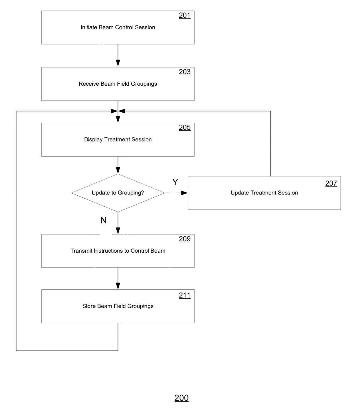
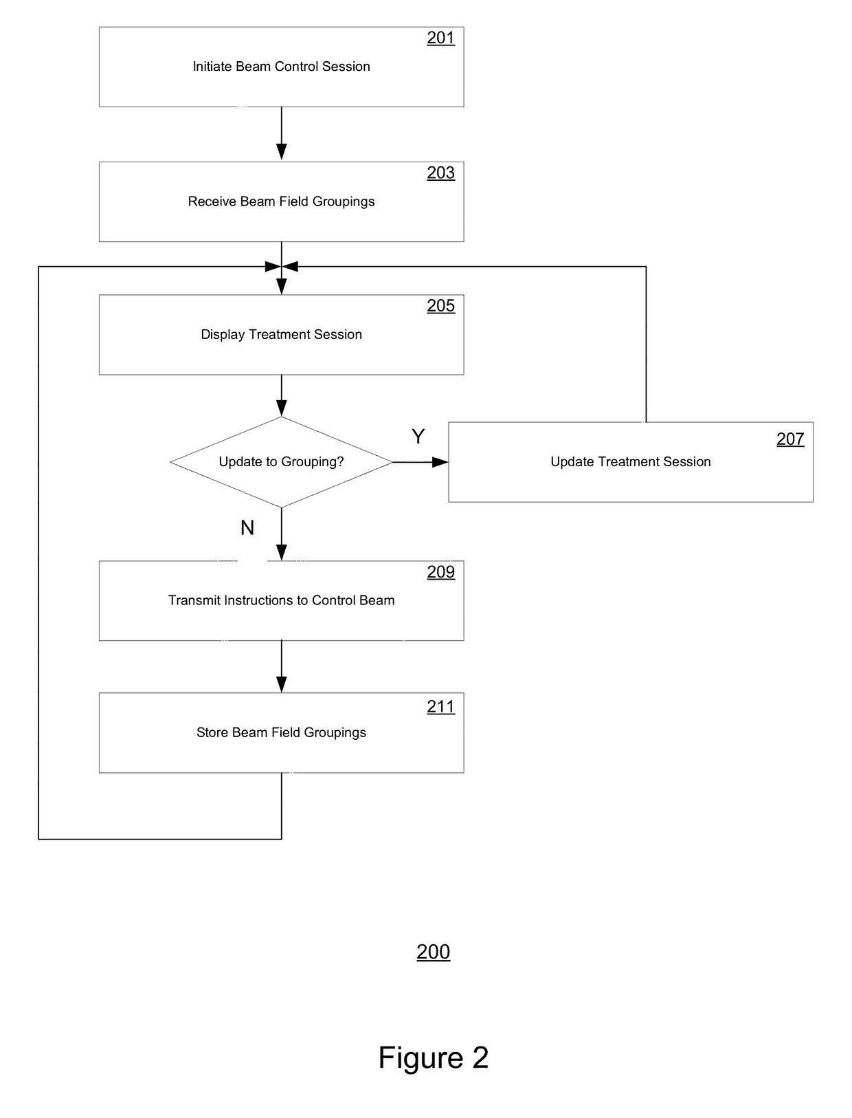
[0007]To overcome the difficulties inherent in conventional proton therapy systems, new techniques for automating, organizing, and graphically visualizing these procedures are herein provided. A control system is described which provides a user interface that displays a clear graphical representation of relevant data for a proton therapy system for treating multiple beam fields as efficiently as possible. The user interface allows a user to visualize a treatment session, select one or multiple beam fields to include in one or more beam applications, and dissociate beam fields previously grouped if necessary.
[0008]Further embodiments extend the ability to initiate the application of the generated proton therapy beam and the grouping of beam fields to be performed remotely from the treatment room itself, and even automatically, reducing the need for operator or physician to intervene to manually setup every individual treatment field. Additional information, such as the progress of a treatment session for which the beam is currently in use are also clearly and intuitively visualized in a display device remotely displaced from the treatment room or area.
[0009]According to a second aspect of the invention, a method for displaying and receiving information corresponding to associating and disassociating beam fields in a graphical user interface is described. Proton beam delivery to treatment fields are automated according to the arrangement of the beam fields, thereby reducing the time a practitioner or therapist requires to prepare a patient or target treatment area between treatment fields.
[0010]By utilizing the systems and methods described above, a user is able to intuitively and efficiently perform the requisite functions to group multiple beam fields for automatic proton beam delivery to a treatment room in either a dedicated or shared beam facility. These functions—all of which can be performed within a single, integrated user-interface remotely from a treatment room—include a graphical environment for the arrangement of beam fields for one or more beam applications of a treatment session, or dissociation of previously associated beam fields. In a shared-beam proton therapy system, the grouping function can work in conjunction with a capable beam queuing and allocating function, wherein a grouping can also serve as one basis for forming a proton beam request with duration sufficient to permit treatment of the set of fields to completion.

Problems solved by technology

These setups can require manual manipulations in the treatment room, manual preparations at the treatment console, or both, with time consumed between each treatment field for manual processes.
For either single-room or shared-beam facilities, extra time consumed by manual field setups can unnecessarily lengthen treatment sessions, and that can negatively affect patient comfort.
Since cyclotrons operate only at a fixed energy during a treatment session, irradiating different depths can become problematic.
For multiple beam fields, this can cause significant delays and additional discomfort for the treatment subject.
Moreover, due to the complexity of the underlying machines, their operating and maintenance procedures, and the gravity of the corresponding medical procedures, highly trained and skilled operators are needed to perform the calculations and actions necessary to make adjustments to a proton therapy device to achieve the desired beam energy and position levels.
Naturally, this can result in further inefficiency, delays or even potential hazards

Method used


Image

  • Method and device for efficiently irradiating a target from multiple irradiation angles in a particle therapy system
  • Method and device for efficiently irradiating a target from multiple irradiation angles in a particle therapy system
  • Method and device for efficiently irradiating a target from multiple irradiation angles in a particle therapy system

Examples


Embodiment Construction

[0019]Reference will now be made in detail to several embodiments. While the subject matter will be described in conjunction with the alternative embodiments, it will be understood that they are not intended to limit the claimed subject matter to these embodiments. On the contrary, the claimed subject matter is intended to cover alternative, modifications, and equivalents, which may be included within the spirit and scope of the claimed subject matter as defined by the appended claims.

[0020]Furthermore, in the following detailed description, numerous specific details are set forth in order to provide a thorough understanding of the claimed subject matter. However, it will be recognized by one skilled in the art that embodiments may be practiced without these specific details or with equivalents thereof. In other instances, well-known processes, procedures, components, and circuits have not been described in detail as not to unnecessarily obscure aspects and features of the subject m...


PUM


Abstract

A control system is described which provides a user interface that displays a clear graphical representation of relevant data for a particle radiation therapy system (such as a pencil-beam proton therapy system) for treating multiple beam fields as efficiently as possible. The user interface allows a user to visualize a treatment session, select one or multiple beam fields to include in one or more beam applications, and dissociate beam fields previously grouped if necessary. Further embodiments extend the ability to initiate the application of the generated proton therapy beam and the grouping of beam fields to be performed remotely from the treatment room itself, and even automatically, reducing the need for manual interventions to setup between fields.

Description

TECHNICAL BACKGROUND[0001]Proton therapy is a type of external beam radiation therapy that is characterized by the use of a beam of protons to irradiate diseased tissue. The chief advantage of proton therapy over other conventional therapies such as X-ray or neutron radiation therapies is the ability to administer treatment dosages three-dimensionally by specifying the depth (i.e., limiting the penetration) of applied radiation, thereby limiting the inadvertent exposure of non-target cells to the potentially harmful radiation. This enables proton therapy treatments to more precisely localize the radiation dosage relative to other types of external beam radiotherapy. During proton therapy treatment, a particle accelerator—such as a cyclotron—is used to generate a beam of protons from, for example, an internal ion source located in the center of the cyclotron. The protons in the beam are accelerated (via a generated electric field), and the beam of accelerated protons is subsequently ...

Claims


Application Information

Patent Timeline
Patent Type & Authority Patents(United States)
IPC IPC(8): A61N5/10
CPCA61N5/1081A61N5/1049A61N2005/1087A61N5/1079A61N5/1082A61N2005/1074
Inventor BENNER, ANKECLIFT, JULIEHENSEL, ANDREASKANE, RICHARDKARIS, JANSINHA, NILESHSPATOLA, BRIANTIMMER, JAN
Owner VARIAN MEDICAL SYSTEMS
Learn More