Mixing and grinding mechanism and mixer grinder using the same

a technology of mixing mechanism and mixer grinder, which is applied in the direction of mixing, rotary stirring mixer, transportation and packaging, etc., can solve the problems of increasing manufacturing cost, occupying a large factory space, and complicating the manufacturing process, so as to save cost and reduce working space

Active Publication Date: 2017-09-19
CATHAY COATING MFG
View PDF26 Cites 8 Cited by
  • Summary
  • Abstract
  • Description
  • Claims
  • Application Information

AI Technical Summary

Benefits of technology

[0011]By driving the rotating shaft to rotate the rotor and the stirrer, the grinding roll is rotated over the inner barrel wall of the barrel to grind the fluid paint of slurry therein. At the same time, the stirrer is synchronously rotated to mix and propel the fluid paint or slurry, forcing the fluid paint or slurry to circulate through the accommodation chamber of the barrel. Thus, the invention achieves the effects of: (1) one machine provides two functions (2 in 1), i.e., a mixer and a grinder are integrated into one unit, saving the cost and reducing working space; (2) when mixing and grinding a fluid paint or slurry, other materials can be added for mixing and grinding when desired.

Problems solved by technology

(1) The roller mill 10 and the paint-mixer machine 20 are two separate machines. Similar designs of the roller mill 10 can be seen in U.S. Pat. No. 258,027; U.S. Pat. No. 3,208,677; U.S. Pat. No. 2,872,122. Similar designs of the paint-mixer machine 20 can be seen in U.S. Pat. No. 6,290,386; U.S. Pat. No. 2,137,547; U.S. Pat. No. 401,306; U.S. Pat. No. 8,616,762; U.S. Pat. No. 2,027,297; U.S. Pat. No. 4,730,938. Thus, various independent machines need to be installed in the manufacturing line, increasing the manufacturing cost and occupying much factory space.
(2) In the adjusting and toning step, pigments may need to be applied, however, the stirrer 202 of the paint-mixer machine 20 (see FIG. 1) does not provide a grinding function. Similar designs of the structure of the stirrer 202 can be seen in U.S. Pat. No. 7,384,188; U.S. Pat. No. 2,636,643; U.S. Pat. No. 4,926,390; U.S. Pat. No. 1,775,345. According to the aforesaid prior art design, another grinder is needed to grind pigments before they are added to the paint-mixer machine 20, thus complicating the manufacturing process.
(3) After the grinding through the roller mill 10, a part of the material may not have been finely ground, however, in the mixing operation through the paint-mixer machine 20, the material cannot be ground into fine grade.

Method used


Image

  • Mixing and grinding mechanism and mixer grinder using the same
  • Mixing and grinding mechanism and mixer grinder using the same
  • Mixing and grinding mechanism and mixer grinder using the same

Examples


Embodiment Construction

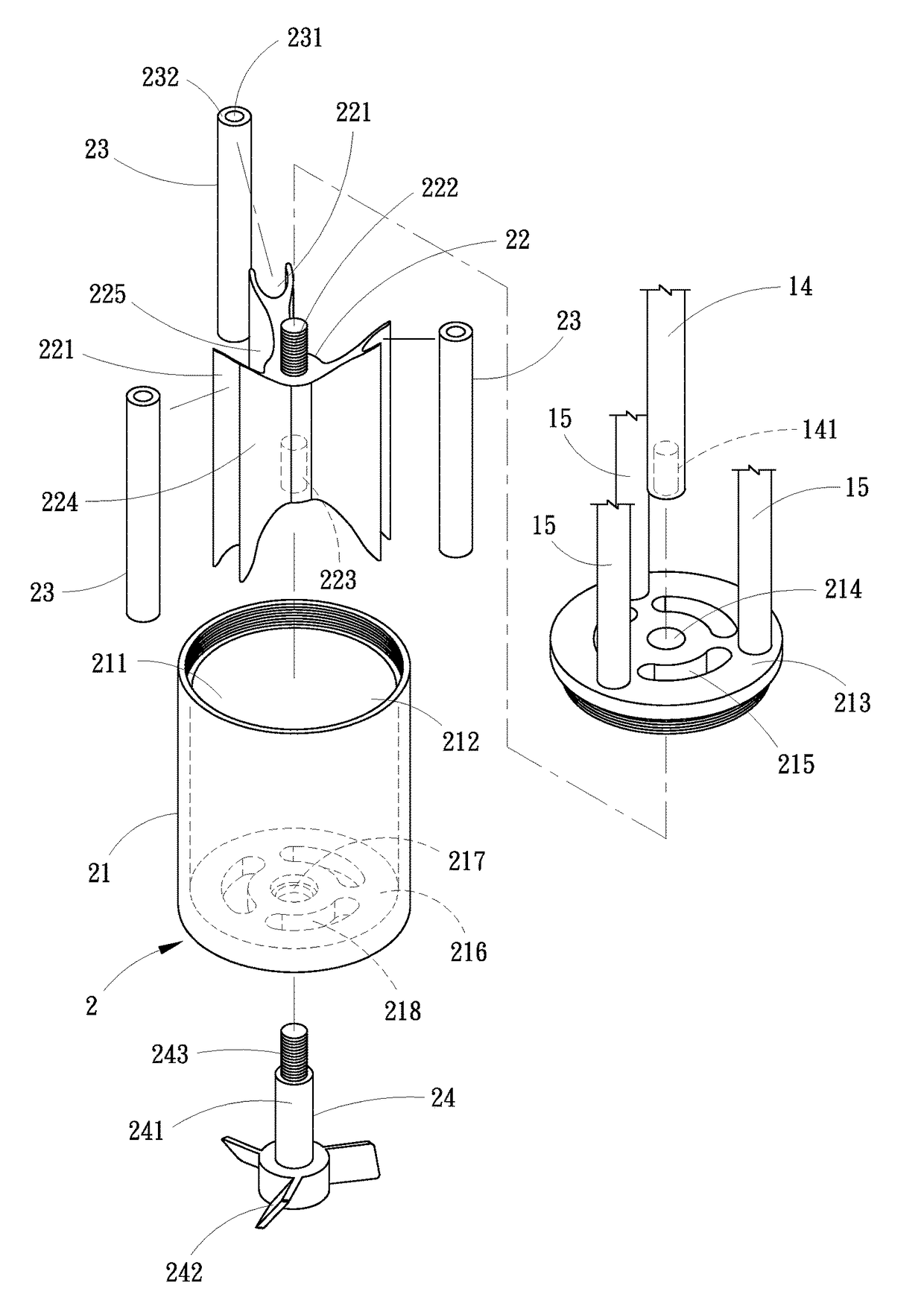
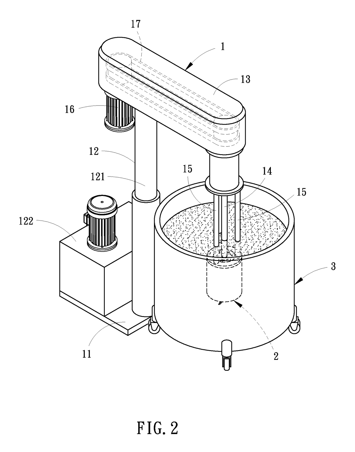
[0023]Referring to FIG. 2, a mixer grinder 1 in accordance with the present invention is shown for mixing and grinding a fluid paint or fluid slurry. The mixer grinder 1 generally comprises a machine base 11, an upright post 12 vertically upwardly located at the machine base 11, a suspension arm 13 horizontally mounted at a top end of the upright post 12 above the machine base 11, a rotating shaft 14 rotatably mounted in a front bottom side of the suspension arm 13, at least one, for example, a plurality of locating rods 15 fixedly mounted at the front bottom side of the suspension arm 13 around the rotating shaft 14, a drive motor 16 fixedly mounted at a front end (or rear end) of the suspension arm 13, and a grinding and mixing mechanism 2 connected to the locating rods 15 and rotatable by the rotating shaft 14 to mix and grind a fluid paint or fluid slurry in a container 3. The drive motor 16 can be configured to rotate the rotating shaft 14 directly. In this embodiment, the driv...


PUM

PropertyMeasurementUnit
outer perimeteraaaaaaaaaa
perimeteraaaaaaaaaa
coloraaaaaaaaaa

Abstract

A grinding and mixing mechanism for mixing and grinding fluid paint or fluid slurry includes a barrel, a rotor rotatably mounted in the barrel, grinding rolls rotatably mounted in the outer perimeter of the rotor and rotatably kept in contact with the inner barrel wall of the barrel for grinding a fluid paint or slurry, and a stirrer connected to the rotor for synchronous rotation with the rotor to mix the fluid paint or slurry circulated through the barrel. The invention also provides a mixer grinder using the grinding and mixing mechanism.

Description

BACKGROUND OF THE INVENTION[0001](a) Field of the Invention[0002]The present invention relates to mixing and grinding technologies, and more particularly to a mixing and grinding mechanism for mixing and grinding fluid paint or other fluid slurry. The invention relates also to a mixer grinder using the mixing and grinding mechanism.[0003](b) Description of the Prior Art[0004]Various different paints and slurries are known. A paint manufacturing process generally includes: (1) material mixing step to mix pigments, resins, additives, solvents in a mixer; (2) material grinding step to grind the mixed materials into a uniformly distributed status with a roller mill 10 (see FIG. 1) or ball mill machine; (3) adjusting and toning step to adjust the viscosity and color the material thus obtained in step (2) in a mixing barrel 201 of a paint-mixer machine 20 by a stirrer 202 by means of adding different ratios of solvents to the material; and (4) filtering and packing step.[0005]The applicat...

Claims


Application Information

Patent Timeline
Patent Type & Authority Patents(United States)
IPC IPC(8): B01F3/12B01F7/16B01F7/22B01F13/10B01F27/91
CPCB01F3/1221B01F7/161B01F7/22B01F13/1044B01F2013/1086B01F2215/005B01F23/53B01F27/806B01F27/91B01F33/8305B01F33/83613B01F2101/30
Inventor JUAN, KUANG-NAN
Owner CATHAY COATING MFG
Why Eureka
Try Eureka