Shoe part shaping insert to be placed in a mold

a molding and shoe technology, applied in the field of shoe part shaping inserts to be placed in molds, can solve the problems of complex molds, unsuitable inserts, and inability to produce several shoe parts, and achieve the effect of increasing the degree of freedom for forming shoe parts

Active Publication Date: 2017-09-19
ECCO SKO
View PDF9 Cites 6 Cited by
  • Summary
  • Abstract
  • Description
  • Claims
  • Application Information

AI Technical Summary

Benefits of technology

[0009]By this arrangement, the injection channel of the insert has the effect of extending the sprue channel to the predefined space. It works as an extension of the sprue channel, whereby the melt can be directed to any cavity defined in the mould. The connection between the sprue channel and the injection channel is fluidtight. As the outlet of the injection channel by this arrangement also is placed inside the mould and on a surface not visible when the shoe is manufactured, there will be no impression scar of the melt inlet as this will be covered by following injections.
[0011]With the described arrangements, a multi-density shoe part and shoe sole can be manufactured without the use of differently shaped bottom pistons or different removable moulds. Thus, the invention enables changes in the material composition for a sole without having to produce new mould parts. It is cost efficient and saves times and makes it easy to change the design and provide shoes with new features, whenever wanted.
[0024]In a further preferred embodiment of the invention, the upper insert part is made in a silicone or rubber material and the lower insert part is made in, glass fibre, aluminium or nylon. This is a suitable material for making the insert. The lower part is made in a hard and wear resistant material. This is convenient as the injection channel is preferable placed in this part. The upper part is made in a more flexible material and secures that a tight interface between the two insert parts takes place.
[0035]By this arrangement, the insert comprises more than two insert parts, whereby it is possible to make two injection channels placed differently from each other in a vertical direction and also to form two cavities, where the cavity formed by one insert part is independent of the cavity formed by the other insert part. Thereby, the degree of freedom for forming shoe parts has been significantly increased.
[0036]In a further preferred embodiment of the invention, the shoe part shaping insert comprises at least one further insert part, said insert part being provided to be placed with a surface facing the lower first surface and an injection channel being provided between the two surfaces, when the two surfaces abut each other. Thereby, the degree of freedom for forming shoe parts has been even more increased.

Problems solved by technology

A drawback of this solution is that it always requires two injection channels placed in the mould, which makes the mould complicated and more expensive compared to a mould provided with only one channel.
Furthermore, the method and the insert are not suitable for producing sole parts placed at the under-surface of the outsole and are not suitable for producing several shoe parts.
Further, the method will induce a melt scar in a heel cap when the method is used for producing such a shoe part, due to the injection channel placed in the mould and the outlet corresponding to the visible back surface of the heel cap.

Method used


Image

  • Shoe part shaping insert to be placed in a mold
  • Shoe part shaping insert to be placed in a mold
  • Shoe part shaping insert to be placed in a mold

Examples


first embodiment

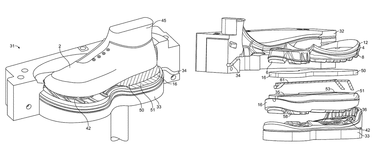
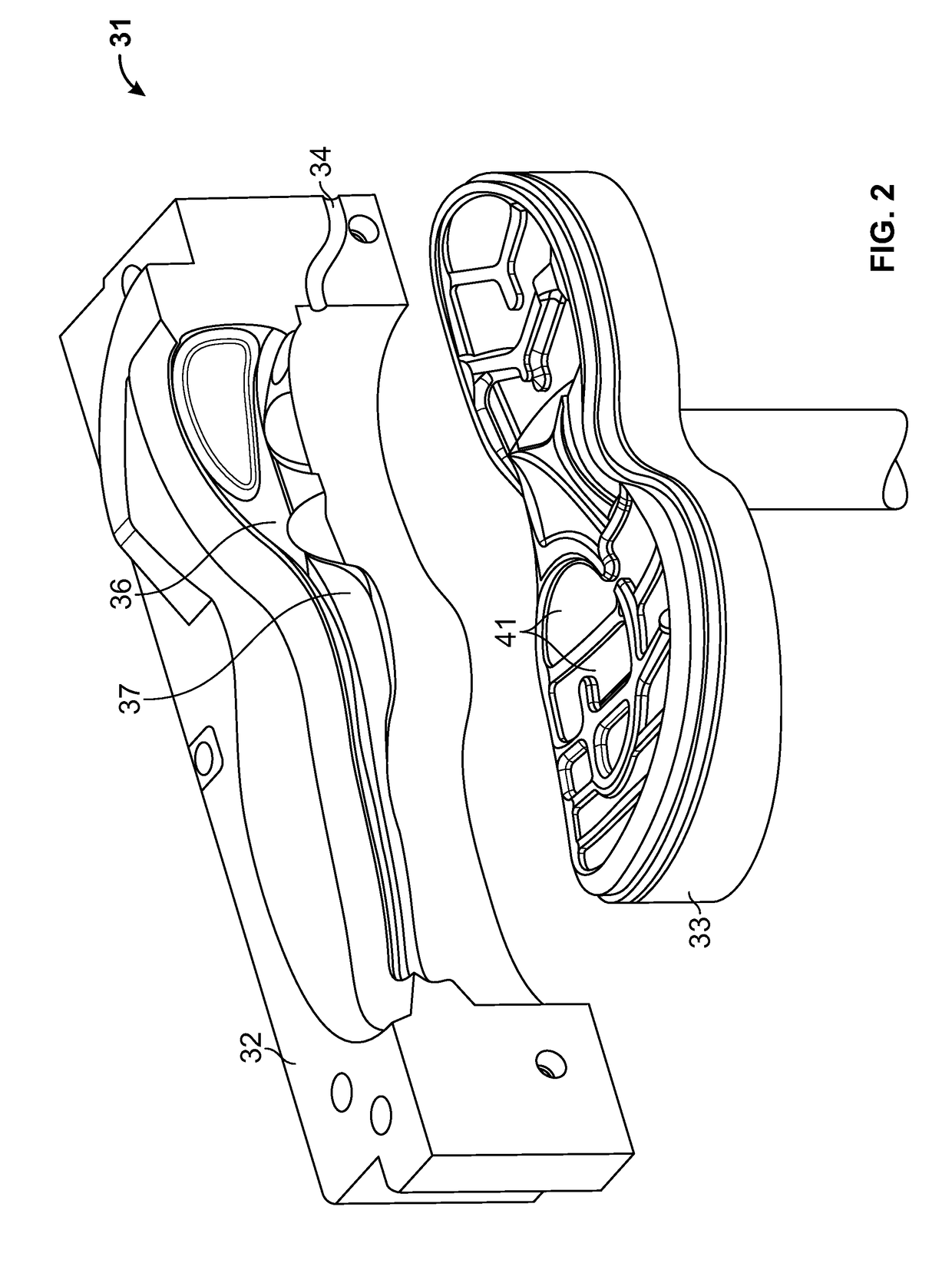
[0059]The entire body of the sole part shaping insert 16 is placed inside the injection chamber and is releasably mounted in the treat pattern of the bottom piston 33. The first injection with polyurethane is made through a sprue channel 34. The polyurethane will flow through an injection channel in the insert and inside the mould. The polyurethane will stay in the first cavity 36 and surround the U-shaped heel of the upper 2 to build a heel cap 5. After the first injection, the two side frames are moved horizontally away from the lasted upper, which now has a heel cap bonded to it and the lasted upper 2 is lifted from the mould. The insert 16 is removed from the upper by the operator and the sprue of the polyurethane heel cap is removed. The insert 16 comprises two parts; an upper insert part 50 and a lower insert part 51. The two parts are separated in order to remove the cured material in an injection channel placed in the interface of the two insert parts 51, 50. This first embo...

second embodiment

[0068]FIG. 5 shows the insert 16 according to the invention; the insert 16 may follow after the heel cap as shown in FIG. 4 has been produced or it may be the first insert placed in order to produce parts of the sole. A segmented more density sole 12 can be made by injecting polyurethane through the injection channel 35. The cavity 36 comprises two separate areas each communicating with a side channel 53 of the insert 16. The channels 53 of the insert are made in the surface of the lower insert part 51 and comprise horizontally and vertically oriented channel parts. The upper insert part 50 covers the injection channel 35 placed in the lower insert part 51. The drawing also shows the print 61 of the whole injection path. The insert comprises two side channels directed vertically downwards having their outlets at the lower first surface 58 of the lower insert part 51. The melt is directed into the cavity 36, placed in the bottom piston 33 and delimited by the lower first surface 58 a...

third embodiment

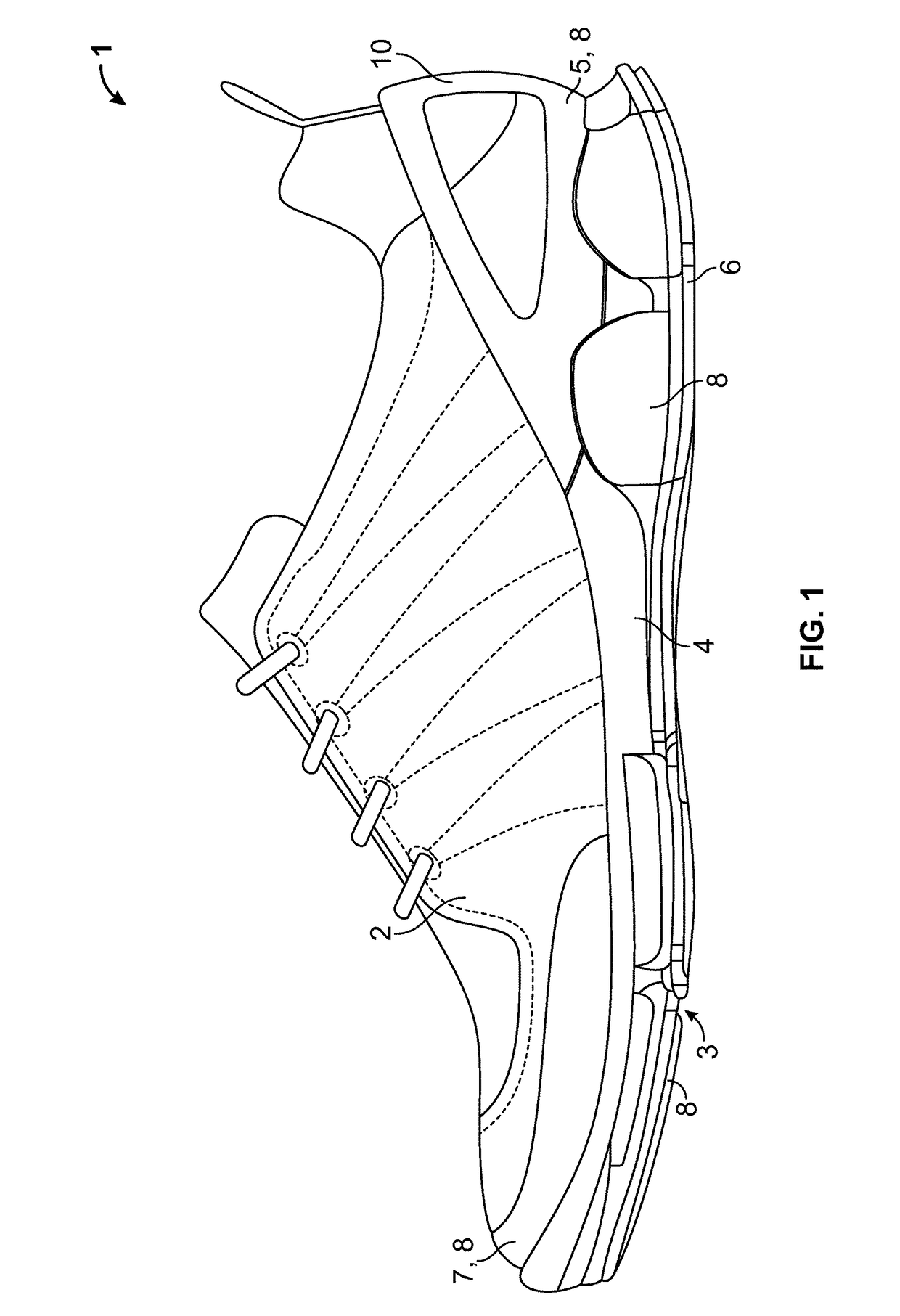
[0069]FIG. 6 shows an insert 16 according to the invention comprising an injection channel 35 and several side channels 53. Four side channels 53 are shown in this example; however, it could be more. The side channels 53 can also point upwards and not only downwards. In case the side channels are pointing upwards, they will of course run through the upper insert part 50. However, in this example the side channel 53 open up at the lower first surface 58 of the lower insert part 51. Thereby, the melt is injected into the cavity providing four shoe parts 8. The drawing also shows a print 61 of the cured melt in the injection path and the final produced sole 12 comprising the shoe parts 8. The shoe parts are specific parts of the outsole 6 having other mechanical properties than the rest of the outsole 6.

[0070]However, the removed insert 16 could be exchanged with another insert 16, whereby a new specific cavity is provided into which a material is injected. Thereby, another shoe part(s...


PUM

PropertyMeasurementUnit
densityaaaaaaaaaa
areaaaaaaaaaaa
perimeteraaaaaaaaaa

Abstract

The invention relates to a method for manufacturing a shoe part by injection molding a material into a mold where an insert is placed. The insert comprises at least two separable insert parts, an upper insert part and a lower insert part, providing an injection channel in the region of the separation area between the two parts. The insert is placed in the chamber and the injection material is injected through a sprue channel in the mold into the injection channel and into a cavity, whereby the shoe part is formed. The mold is opened after the injection material has cured and the insert is separated into the upper and lower insert parts, thereby exposing the cured material in the injection channel.

Description

[0001]This is a National Phase Application filed under 35 U.S.C. 371 as a national stage of PCT / DK2013 / 050259, filed Aug. 6, 2013, claiming priority from Denmark Application No. PA 2012 70509, filed Aug. 28, 2012, the content of each of which is hereby incorporated by reference in its entirety.TECHNICAL FIELD[0002]The invention relates to a method for manufacturing one or more shoe parts by injection moulding of a material onto a shoe upper mounted on a last and injecting said material into a mould comprising a vertically moveable bottom piston and side frames, said mould providing a chamber for injection moulding the shoe part(s) and for placing a shoe part shaping insert in said mould. The invention also relates to a shoe-part shaping insert.BACKGROUND[0003]WO 2011 / 054509 describes a method for manufacturing a multi-density shoe sole comprising repeated injections of sole material onto a shoe upper mounted on a last and placed in a mould. The method includes an insert placed in th...

Claims


Application Information

Patent Timeline
Patent Type & Authority Patents(United States)
IPC IPC(8): B29C45/26A43B1/00B29D35/14B29D35/08A43B23/17B29D35/00A43B13/12
CPCB29D35/0018A43B1/0027A43B13/12A43B23/17B29C45/26B29C45/2673B29C45/2675B29D35/0027B29D35/081B29D35/142
Inventor HANSEN, HANS CHRISTIAN
Owner ECCO SKO
Why Eureka
Try Eureka