Screw spindle pump

a spindle pump and spindle technology, which is applied in the direction of intermeshing engagement type engines, rotary piston engines, rotary or oscillating piston engines, etc., can solve the problems of increased leakage of the pump, unusable movement of the spindle, and disadvantageous effects, so as to reduce the drive torque required

Active Publication Date: 2017-09-19
LEISTRITZ PUMPEN
View PDF9 Cites 6 Cited by
  • Summary
  • Abstract
  • Description
  • Claims
  • Application Information

AI Technical Summary

Benefits of technology

[0004]Although this fuel pump has been found to be advantageous for many decades, it has been found that, under specific conditions, depending on component tolerances and pressure relationships, an undesirable movement of the spindles may occur. This movement is undefined or irregular; it primarily involves crossing of the spindles. This crossing results in the longitudinal axes of the at least two spindles not being arranged in a precisely parallel manner but instead forming an angle with each other, Therefore, the longitudinal axes of the at least two spindles can also be displaced or crossed with respect to a notional plane in which both longitudinal axes are ideally located, one spindle protruding from one side of the notional plane and the other spindle from the opposing side of the notional plane. This spindle movement which may be observed leads to disadvantageous effects. On the one hand, the profile gaps increase, primarily at the intake side of the screw spindle pump, whereby the leakage of the pump increases. This occurs in particular at elevated medium temperatures, which leads to impaired heat conveying behaviour. The increase of the profile gaps also leads, on the other hand, to a reduction of the degree of efficiency. In addition, the undefined movement of the spindles brings about increased suction pulsation which is also undesirable. The rolling line formed between the two or more spindles is influenced in a negative manner by friction effects, whereby the drive torque which has to be applied by the electric motor is increased. Furthermore, the undesirable wobble movement of the spindles also leads to increased wear.
[0005]FIG. 1 shows a plate I of a conventional screw spindle pump, The plate 1 is in the form of a feather key and has a planar upper side 2, The two arrows 3, 4 symbolically represent the longitudinal axes of a drive spindle and a running spindle. In FIG. 1, it can be seen that the two spindles carry out a wobble movement at the upper side 2, that is to say, the ends of the spindles “travel” which results in an oblique position which can be seen particularly well in FIGS. 2 and 3. In FIG. 2, it can be seen that the spindles starting from a parallel starting position at the intake side of the screw spindle pump, at the upper side 2 of the plate 1, have moved apart. FIG. 3 is a view of FIG. 2 rotated through 90° and it can be seen here that the spindles have also moved in a non-uniform manner relative to a notional plane in which ideally parallel spindle axes are located so that the spindle 4 is located in front of this notional plane and the other spindle 3 is located behind this notional plane.SUMMARY OF THE INVENTION
[0006]An object of the invention is therefore to provide a screw spindle pump in which no wobble movement of the spindles occurs.
[0007]In order to achieve this object, in a screw spindle pump of the type mentioned in the introduction, there is provision according to the invention for the plate to have two faces which are inclined in opposing directions relative to each other and which form a V-shape and on which one of the spindles is supported, respectively.
[0008]The inclination of the faces provided according to the invention counteracts a crossing of the spindles. A highly precisely parallel orientation of the spindles is thus ensured, whereby the problems described are prevented. The inclined faces result in the end portions of the at least two spindles always being subjected to a force which is directed toward the other, whereby a wobble movement which occurs with conventional spindle screw pumps is prevented. At the end portion of the spindles, consequently, at least a small force acts in the transverse direction, whereby the spindles are retained at the ideal position,
[0009]With the screw spindle pump according to the invention, it is particularly preferable for the inclination of the faces to be selected in such a manner that the spindles are arranged parallel with each other during operation of the screw spindle pump. As a result of this parallel positioning, there is produced an optimum rolling line between the spindles, whereby the drive torque required is reduced.

Problems solved by technology

Although this fuel pump has been found to be advantageous for many decades, it has been found that, under specific conditions, depending on component tolerances and pressure relationships, an undesirable movement of the spindles may occur.
This spindle movement which may be observed leads to disadvantageous effects.
On the one hand, the profile gaps increase, primarily at the intake side of the screw spindle pump, whereby the leakage of the pump increases.
This occurs in particular at elevated medium temperatures, which leads to impaired heat conveying behaviour.
The increase of the profile gaps also leads, on the other hand, to a reduction of the degree of efficiency.
In addition, the undefined movement of the spindles brings about increased suction pulsation which is also undesirable.
Furthermore, the undesirable wobble movement of the spindles also leads to increased wear.

Method used


Image

  • Screw spindle pump
  • Screw spindle pump
  • Screw spindle pump

Examples


Embodiment Construction

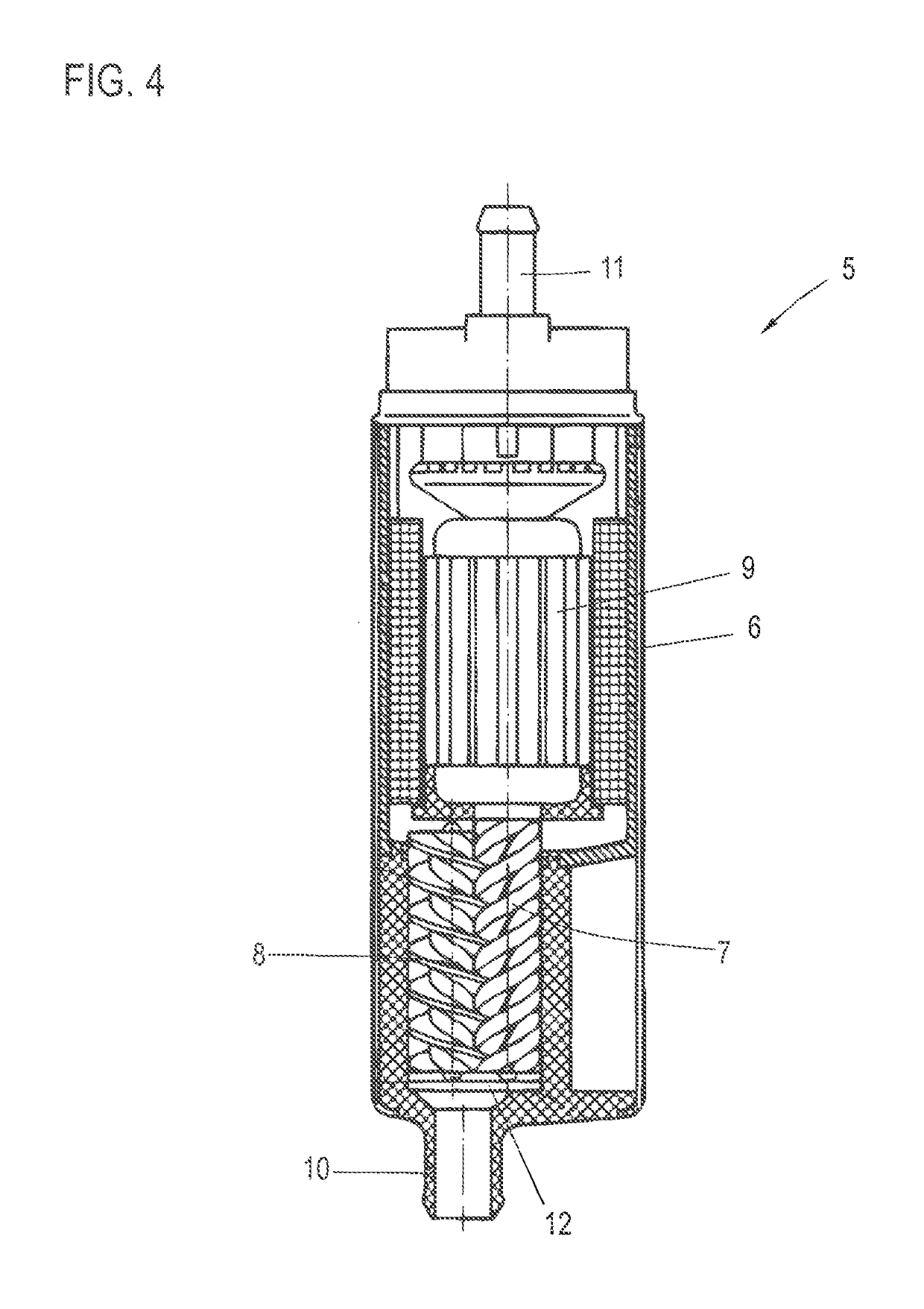
[0032]FIG. 4 shows the significant components of a screw spindle pump 5, comprising a housing 6, in which a drive spindle 7 and a running spindle 8 are received. Both spindles have profile assemblies which mesh with each other. An electric motor 9 drives the drive spindle 7; by means of the opposing rotation of the two spindles 7, 8, a fluid, for example, a fuel for a combustion engine, is drawn through an intake nozzle 10. The fluid flows through the electric motor 9 and leaves the housing 6 via an outlet 11.

[0033]The free end of the drive spindle 7 and the end portion of the running spindle 8 are supported on a plate 12 which is arranged in the housing 6 transversely relative to the spindles. At both sides of the plate 12, there is provided a free space which is delimited by the housing 6 so that the fluid can flow in through these free spaces.

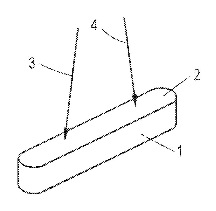
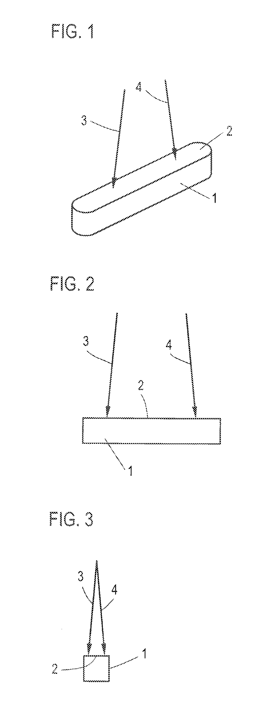
[0034]FIG. 5 is a perspective view of the plate 12. The plate 12 has in a manner corresponding to the plate shown in FIG. 1 the basic shape...


PUM


Abstract

A screw spindle pump having a housing hi which a drive spindle and at least one running spindle having profile assemblies which engage inside each other are received, the free end of the drive spindle and the end portion of the running spindle being supported on a plate which is arranged in the housing, the plate having two faces which are inclined in opposing directions relative to each other and which form a V-shape and on which one of the spindles is supported, respectively.

Description

CROSS-REFERENCE TO RELATED APPLICATIONS[0001]The present application claims priority of DE 10 2014 102 390.0, filed Feb. 25, 2014, the priority of this application is hereby claimed and this application is incorporated herein by reference.BACKGROUND OF THE INVENTION[0002]The invention relates to a screw spindle pump having a housing in which a drive spindle and at least one running spindle having profile assemblies which engage inside each other are received, the free end of the drive spindle and the end portion of the running spindle being supported on a plate which is arranged transversely in the housing.[0003]Screw spindle pumps of this type are used, for example, as fuel pumps. DE 41 23 384 A1 discloses a fuel conveying unit having a housing in which an electric motor is arranged. The shaft of the electric motor is connected to a drive spindle in a rotationally secure manner, but the transmission of force of the motor to the drive spindle can also be introduced by means of a cou...

Claims


Application Information

Patent Timeline
Patent Type & Authority Patents(United States)
IPC IPC(8): F01C1/16F03C2/08F01C1/24F04C2/08F04C18/08F01C1/08F04C3/08F04C2/16F01C21/10
CPCF04C3/085F01C21/108F04C2/16
Inventor METZ, JURGENZEMANEK, KRIS
Owner LEISTRITZ PUMPEN
Why Eureka
Try Eureka