High precision current sensor

a current sensor, high-precision technology, applied in the direction of dc-ac conversion measurement, magnetic measurement, instruments, etc., can solve the problems that the error correction method of rom cannot be applied to the current sensor for measuring the current of the battery, and it is difficult to correct the measurement error, so as to achieve accurate measurement of a large current

Inactive Publication Date: 2006-03-02
DENSO CORP
View PDF2 Cites 65 Cited by
  • Summary
  • Abstract
  • Description
  • Claims
  • Application Information

AI Technical Summary

Benefits of technology

[0011] In view of the above-described problem, it is an object of the present invention to provide a current sensor with which a large current can be accurately measured.
[0013] In the current sensor, the gaps increase magnetic flux leakage from the core, and thereby magnetic saturation can be prevented. Consequently, the current sensor can accurately measure a large current.
[0015] In the current sensor with two magnetic sensors, a current is calculated on the basis of each output of the two magnetic sensors. The current calculation process corrects a measurement error caused by residual flux, and thereby the current sensor can accurately measure a large current.

Problems solved by technology

However, the error correcting method with ROM cannot be applied to a current sensor for measuring a battery current.
Consequently, it is difficult to correct a measurement error with ROM storing fixed data corresponding to the error.

Method used


Image

  • High precision current sensor
  • High precision current sensor
  • High precision current sensor

Examples


first embodiment

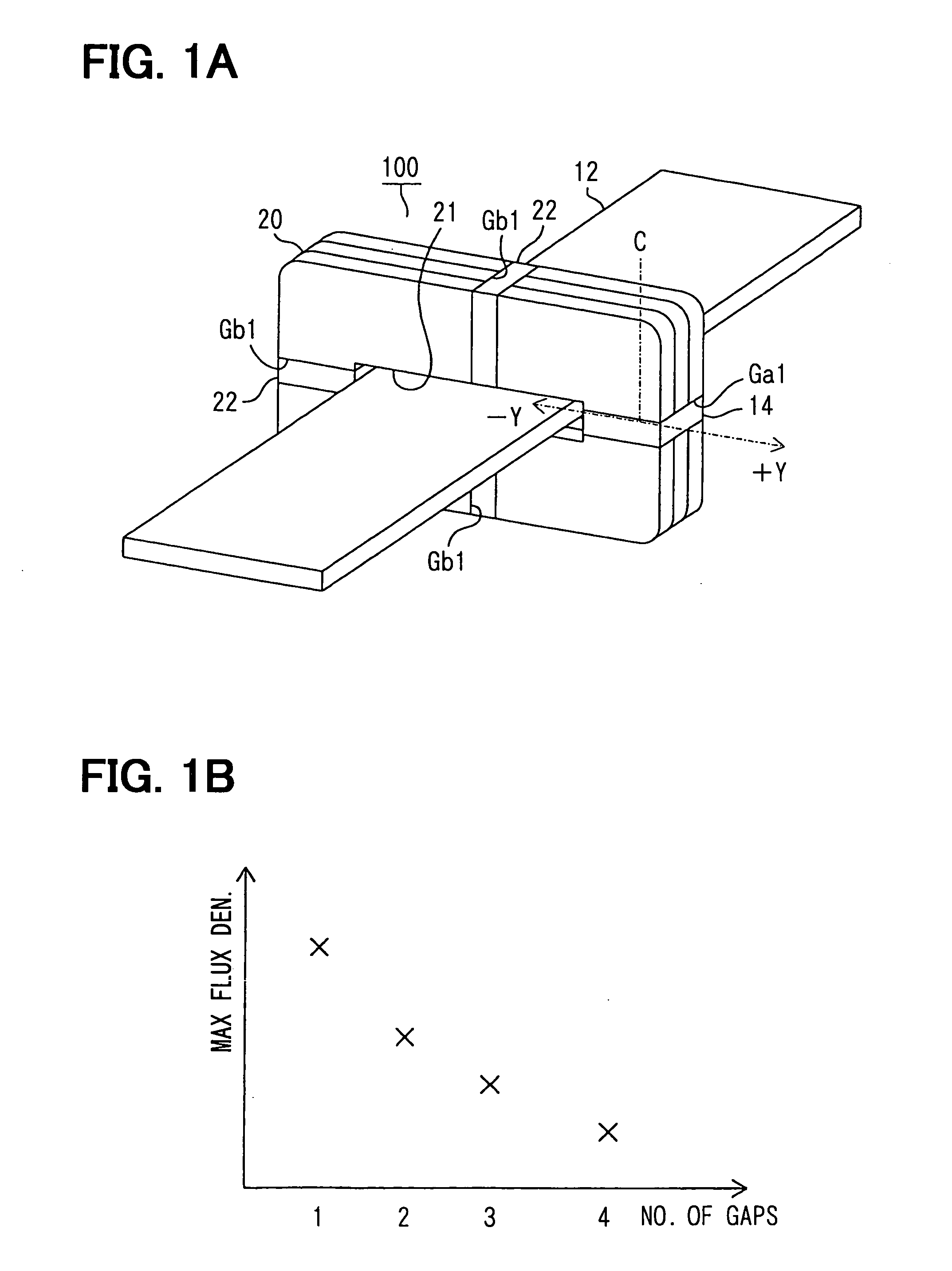
[0034] The inventors have preliminary studies about a current sensor for improving magnetic saturation. There is a potential method for overcoming magnetic saturation. Expanding the width of the gap Ga1 of the sensor 10 increases leakage flux in the core 20, and thereby magnetic saturation can be prevented. However, this method requires that the magnetic sensor 14 is exactly disposed in a center of the gap Ga1. The reason is as follows:

[0035] Graphs illustrated in FIG. 16 show a relation between magnetic flux density and a position in the gap Ga1, when a given amount of current flows. A vertical axis represents magnetic flux density, and a horizontal axis represents a deviation from the center C of the gap Ga1 to ±Y direction. A solid line graph represents the sensor 10 with one gap Ga1. A chain double-dashed line graph represents a wider gap version of the sensor 10. The flat area in the middle of each graph indicates effective sensing area for the magnetic sensor 14. When the mag...

second embodiment

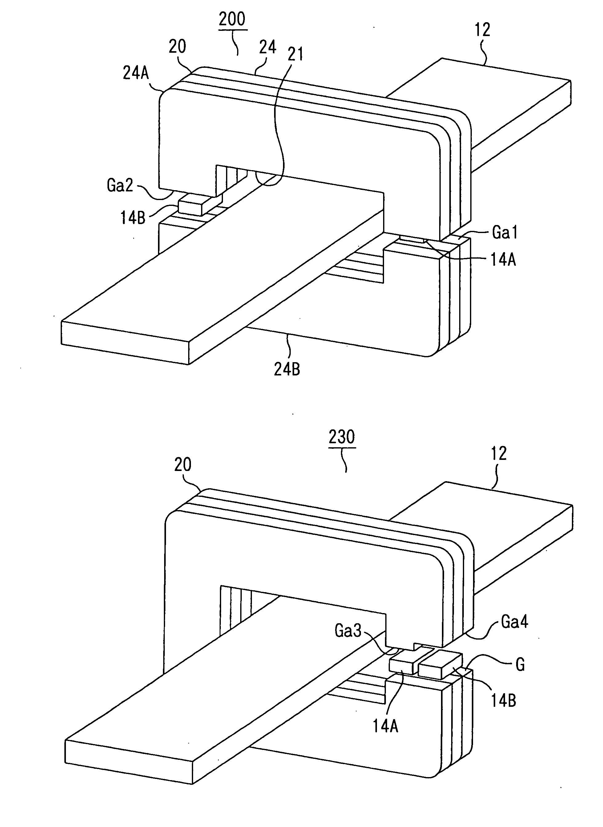
[0055] A current sensor 200 according to a second embodiment of the present invention is shown in FIG. 8A. The sensor 200 is designed to measure a battery current. As shown in FIG. 8A, the sensor 200 includes a magnetic core 20, a current bus bar 12, a first magnetic sensor 14A and a second magnetic sensor 14B. The core 20 has a center opening 21 and two gaps Ga1, Ga2. The core 20 is evenly divided into an upper half 24A and a lower half 24B by the gaps Ga1, Ga2. The magnetic sensor 14A, 14B are disposed in the gaps Ga1, Ga2, respectively. The bar 12 is disposed in a plane perpendicular to the core 20 and inserted in the opening 21 with a given space until the core 20 is positioned in the middle of the bar 12. The magnetic sensors 14A, 14B detect magnetic flux density in the gaps Ga1, Ga2, respectively, generated by a current flowing through the bar 12.

[0056] The same Hall effect devices are employed in each magnetic sensor 14A, 14B as its magnetic sensing element. Consequently, th...

third embodiment

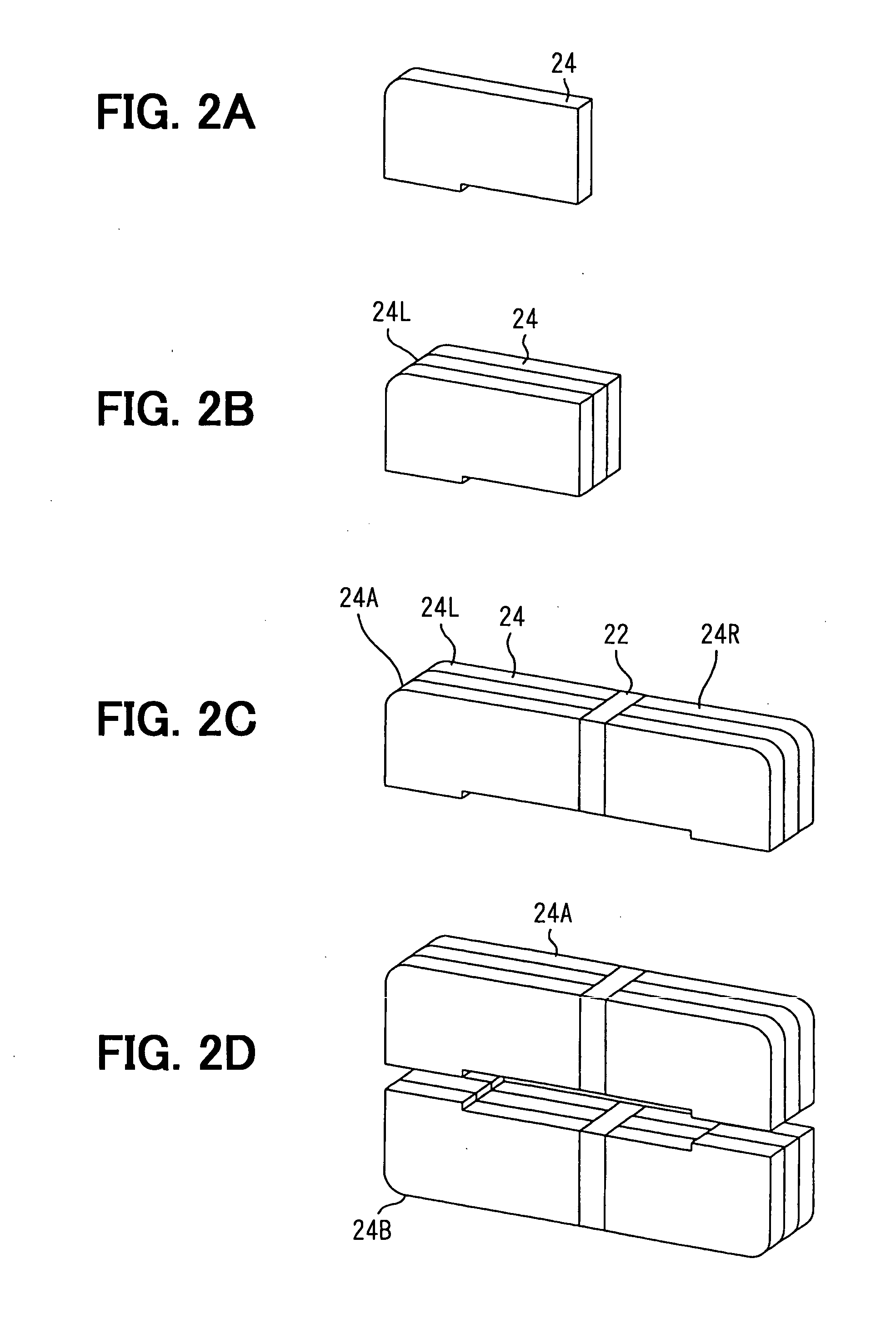
[0082] A current sensor 300 according to a third embodiment of the present invention is shown in FIG. 17. The sensor 300 includes two gaps G, Gb1. One of the gaps G is composed of different width gaps Ga3, Ga4, which is similar to the sensor 230 shown in FIG. 13. The other one of gaps Gb1 is disposed opposite to the gap G, which is similar to the sensor 100 shown in FIG. 1A. Here, the sensor 300 can include multiple gaps Gb1 shown in FIG. 1A. For example, the sensor 300 can include three gaps Gb1.

[0083] Thus, the sensor 300 according to the third embodiment is formed to combine the sensor 100 according to the first embodiment and the sensor 230 according to the second embodiment. Here, in the sensor 100 according to the first embodiment, the magnetic core 20 is divided into multiple parts so that the magnetic saturation is reduced. Therefore, to flow a large current in the core 20, it is required to increase the number of the parts. However, when the sensor 100 includes the large n...


PUM


Abstract

A current sensor for measuring an electric current flowing through a current bus bar includes: a magnetic core with an opening, through which the current bus bar passes with a predetermined interval; and a first magnetic sensor for detecting magnetic flux density in the magnetic core, the magnetic flux density generated by the electric current passing through the current bas bar. The magnetic core has a first gap and a second gap. The first magnetic sensor is disposed in the first gap. The second gap is capable of preventing magnetic saturation of the magnetic core.

Description

CROSS REFERENCE TO RELATED APPLICATIONS [0001] This application is based on Japanese Patent Applications No. 2004-255253 filed on Sep. 2, 2004, and No. 2004-255254 filed on Sep. 2, 2004, the disclosures of which are incorporated herein by references. FIELD OF THE INVENTION [0002] The present invention relates to a current sensor, and more particularly to high precision current sensor with a magnetic sensor. BACKGROUND OF THE INVENTION [0003] Electrical components mounted on automotive vehicles such as car navigation systems have increased in recent years. A current drain on car batteries has become too large accordingly, and a peak current has reached to several hundred amperes. A variety of technologies improving fuel economy have therefore applied to cars. An engine control system, which is one of the technologies, stops to operate a battery-charging generator under acceleration and operates the generator under deceleration. The engine control system requires precision detection c...

Claims


Application Information

Patent Timeline
Patent Type & Authority Applications(United States)
IPC IPC(8): G01R33/00
CPCG01R15/202G01R15/185G01R15/20
Inventor ITOH, TOMOKIISHIHARA, MASATO
Owner DENSO CORP
Why Eureka
Try Eureka