Ultrasonic atomizer and electronic cigarette

a technology of ultrasonic atomizer and electronic cigarette, which is applied in the direction of inhalator, tobacco, tobacco pipes, etc., can solve the problems of high power consumption, heat conduction loss, damage to the health of smokers, etc., and achieve the effect of preventing the atomization piece from being damaged

Active Publication Date: 2018-06-14
CHINA TOBACCO HUNAN INDAL CORP
View PDF2 Cites 55 Cited by
  • Summary
  • Abstract
  • Description
  • Claims
  • Application Information

AI Technical Summary

Benefits of technology

[0015]The electric conductor is in elastic connection with a positive electrode and a negative electrode fixed in the base. The elastic connection can well prevent an open circuit resulting from melt of a bonding pad because of high temperature or vibration generated in a working process of the atomiz

Problems solved by technology

When the temperatures of the heating wires are too high, the tobacco tar guide cotton or fibers and other tobacco tar guide materials are burnt easily to produce harmful substances, which damage the health of smokers, and burnt flavor is produced easily to affec

Method used


Image

  • Ultrasonic atomizer and electronic cigarette
  • Ultrasonic atomizer and electronic cigarette
  • Ultrasonic atomizer and electronic cigarette

Examples


embodiment 1

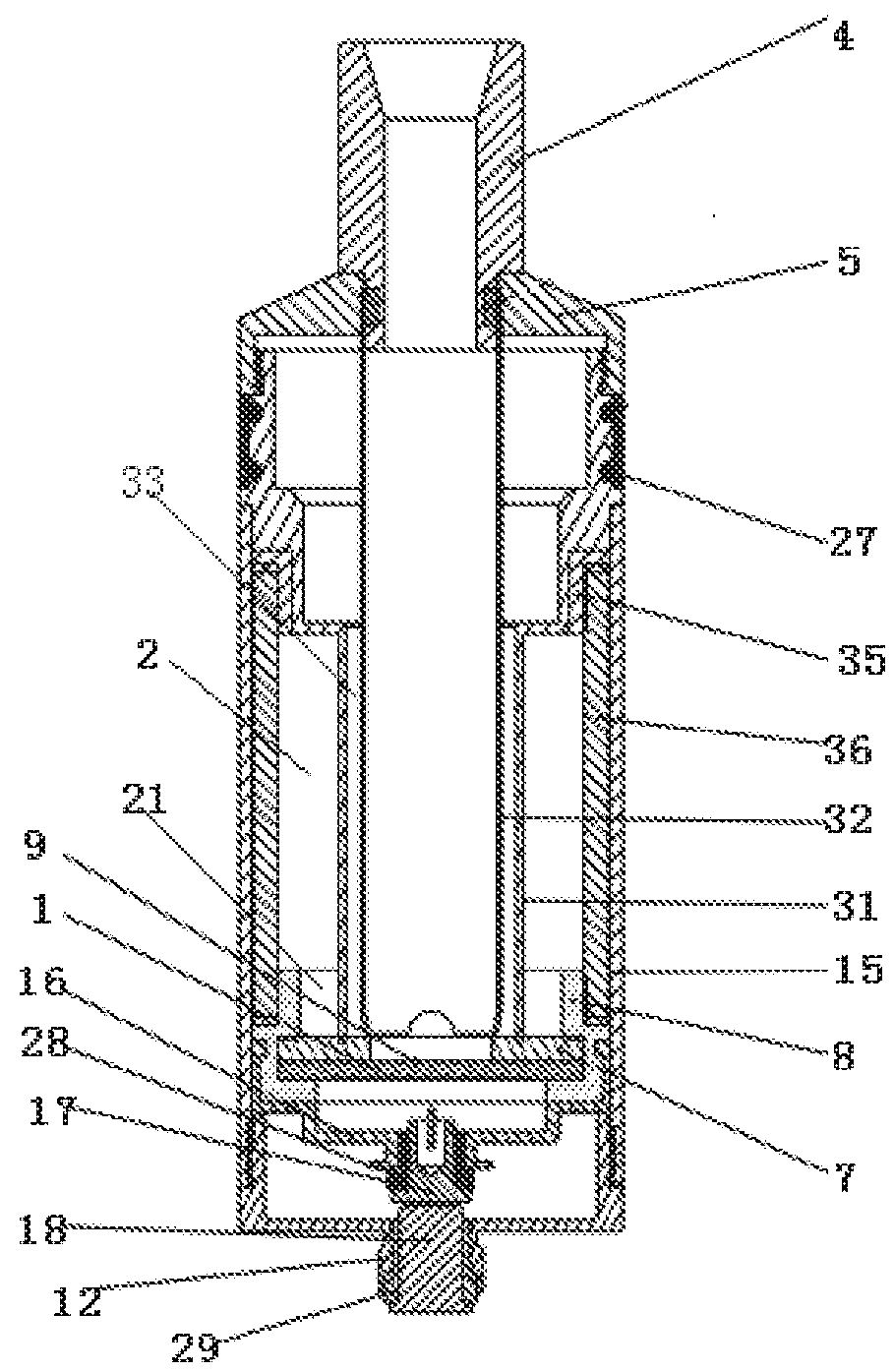
[0038]In embodiment 1, the outer wall of the upper part (one end that is close to the liquid storage cavity) of the silica gel sleeve is in hermetical connection with the inner wall of the bottom end of the liquid storage cavity, the outer wall of the lower part (one end that is away from the liquid storage cavity) of the silica gel sleeve is in contact with the inner wall of an atomization base 16, the outer wall of the atomization base 16 is in contact with the inner wall of the housing 15, and an atomization electrode 17 insulated and isolated (insulated and isolated by an atomization insulation ring 28) from the atomization base 16 is provided in the atomization base 16; the atomization base 16 is in fixed connection with the top end (one end that is close to the atomization piece) of a base 30; the outer wall of the base 12 is in screw connection with the inner wall of the housing 15; and an electrode ring 18 insulated and isolated (insulated and isolated by a base insulation r...

embodiment 2

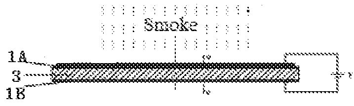
[0041]As shown in FIG. 7, in embodiment 2, the first conducting layer 1A and the second conducting layer 1B are respectively in elastic connection (for example, the elastic connection can be realized by an elastic ejector pin) with a positive electrode 25 and a negative electrode 26 fixed in the base 12; and a main control board 30 is fixed in the base 12, the main control board 30 can detect the temperature of the atomization piece by a temperature sensor 22 and control the start and stop of the atomization piece (the normal working temperature of the atomization piece is 130-220° C. in general, the atomization piece should be stopped once the temperature exceeds 220° C. to prevent the atomization piece from being damaged). In the embodiment, the bottom of the silica gel sleeve is in contact with a compressing block 38, the pressing block 38 can compress silica gel sleeve tightly, and thus the atomization piece is more stable. Both of the compressing block 38 and the silica gel sle...

embodiment 3

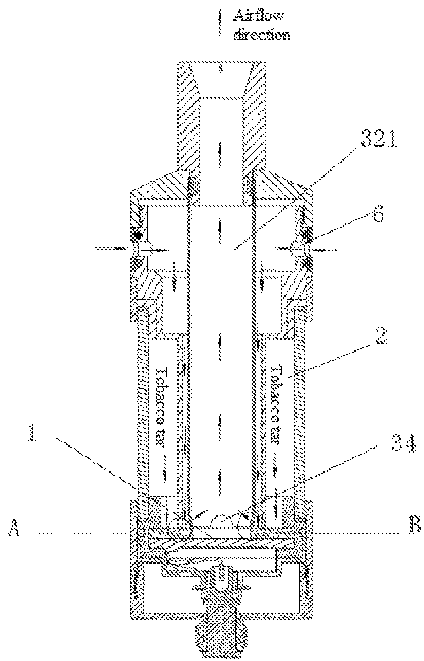
[0044]As shown in FIG. 8 and FIG. 9, in the present invention, the liquid guide structure comprises the porous material 7; the upper surface of the porous material 7 is in contact with the lower surface (one surface that is away from the piezoelectric ceramic layer) of the second conducting layer 1B; a plurality of liquid guide holes 10 are provided in the atomization piece 7; both of the atomization piece 1 and the porous material 7 are provided in a mounting base 11, and the outer wall of the atomization piece 1 is in contact with the inner wall of the mounting base 11 through an elastic sealing base 8; the top end of the mounting base 11 is in fixed connection with the bottom end of the air inlet pipe 31; the bottom end of the mounting base 11 is in fixed connection with the middle (a salient at the middle of the base 12) of the base 12; the lower surface of the porous material 7 is in contact with the upper surface of the middle of the base 12 (i.e., a space between the base 12 ...


PUM


Abstract

The present invention discloses an ultrasonic atomizer and electronic cigarette. The ultrasonic atomizer comprises an atomization piece and a liquid guide structure, which guides liquid onto an upper surface of the atomization piece; the liquid guide structure communicates with a liquid storage cavity; the upper surface of the atomization piece communicates with an airflow passage; and the atomization piece comprises a piezoelectric ceramic layer and an electric conductor, which drives vibration of the piezoelectric ceramic layer. No micropore needs to be provided in the atomization piece of the present invention to eject the atomized gas, thereby being free of the situation that the micropore is blocked by larger atomized gas particles, resulting in that the atomized gas cannot be ejected, and meanwhile the situation of liquid leakage of the atomizer can be better prevented.

Description

TECHNICAL FIELD[0001]The present invention relates to an ultrasonic atomizer and electronic cigarette.BACKGROUND ART[0002]The existing atomizers use heating wires to heat tobacco tar, the tobacco tar or liquid is guided onto the heating wires by tobacco tar guide cotton or fibers. When the temperatures of the heating wires are too high, the tobacco tar guide cotton or fibers and other tobacco tar guide materials are burnt easily to produce harmful substances, which damage the health of smokers, and burnt flavor is produced easily to affect the smoke taste; moreover, part of the heat of the heating wires will be absorbed by the tobacco tar guide materials, thereby resulting in the disadvantages of heat conduction loss, high power consumption and low efficiency, and the atomizers easily become hot.CONTENTS OF INVENTION[0003]The technical problem to be solved in the present invention is to provide an ultrasonic atomizer and an electronic cigarette in view of the shortcomings of the pri...

Claims


Application Information

Patent Timeline
IPC IPC(8): A61M11/00A24F47/00A61M15/00B05B17/06A24F15/015A24F40/05A24F40/10A24F40/485A24F40/60
CPCA61M11/005A24F47/002A61M15/001A61M15/0085B05B17/0661B05B17/0684A24F40/05A24F40/10A24F40/60A24F15/015A24F40/485A24F40/40
Inventor LIU, JIANFUZHONG, KEJUNGUO, XIAOYIHUANG, WEIDAI, YUANGANGYIN, XINQIANGYU, HONGSHEN, LIZHOUWANG, YANG
Owner CHINA TOBACCO HUNAN INDAL CORP
Why Eureka
Try Eureka