
Pressure independent control and balancing valves

a technology of pressure independent control and balancing valve, which is applied in the direction of non-electric variable control, flow control, instruments, etc., can solve the problems of unstable control, excessive pumping energy required to address unnecessary pressure, and user choice of one or another typ

Inactive Publication Date: 2017-09-19
IMI HYDRONIC ENG INT SA
View PDF15 Cites 4 Cited by
  • Summary
  • Abstract
  • Description
  • Claims
  • Application Information

AI Technical Summary

Benefits of technology

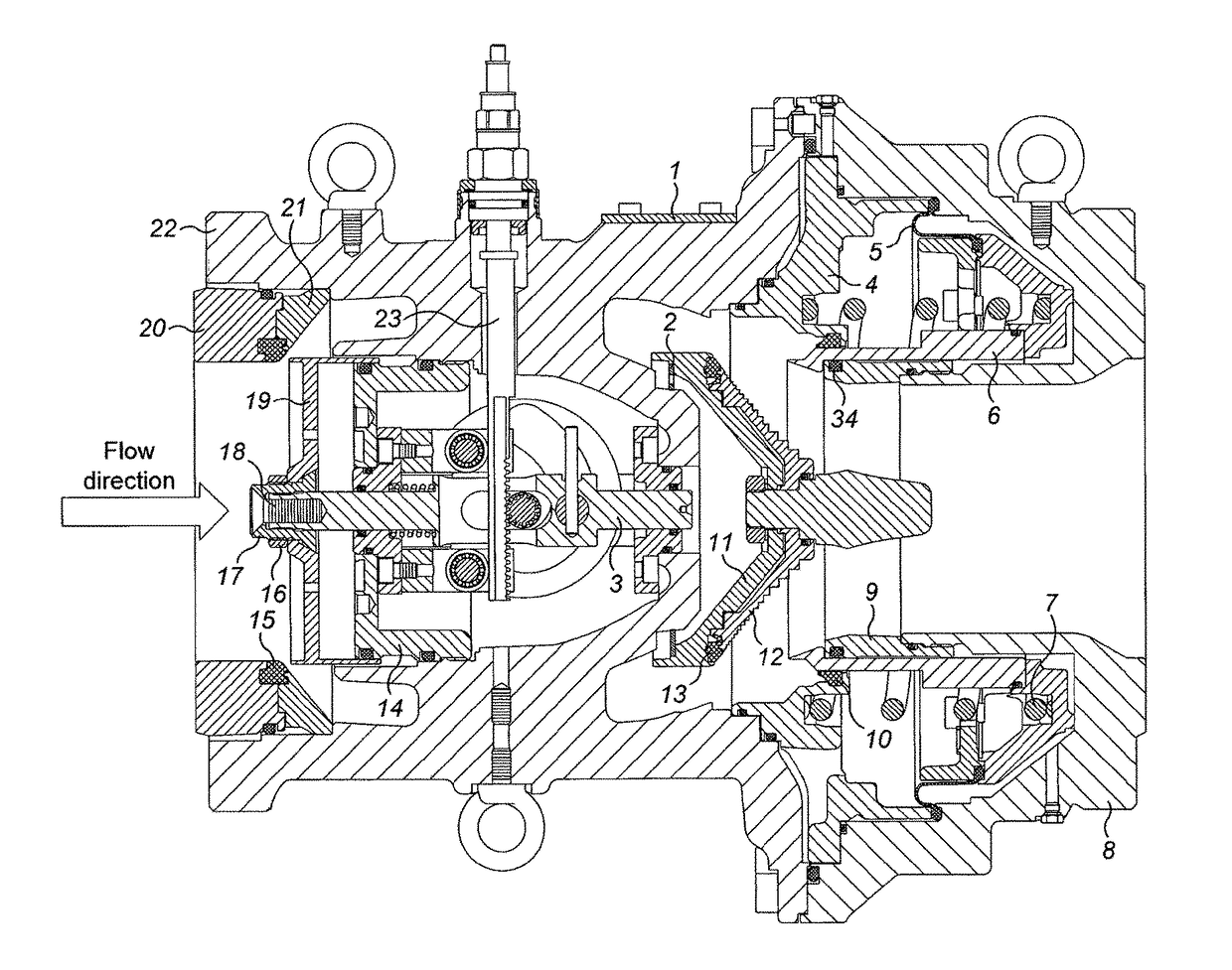
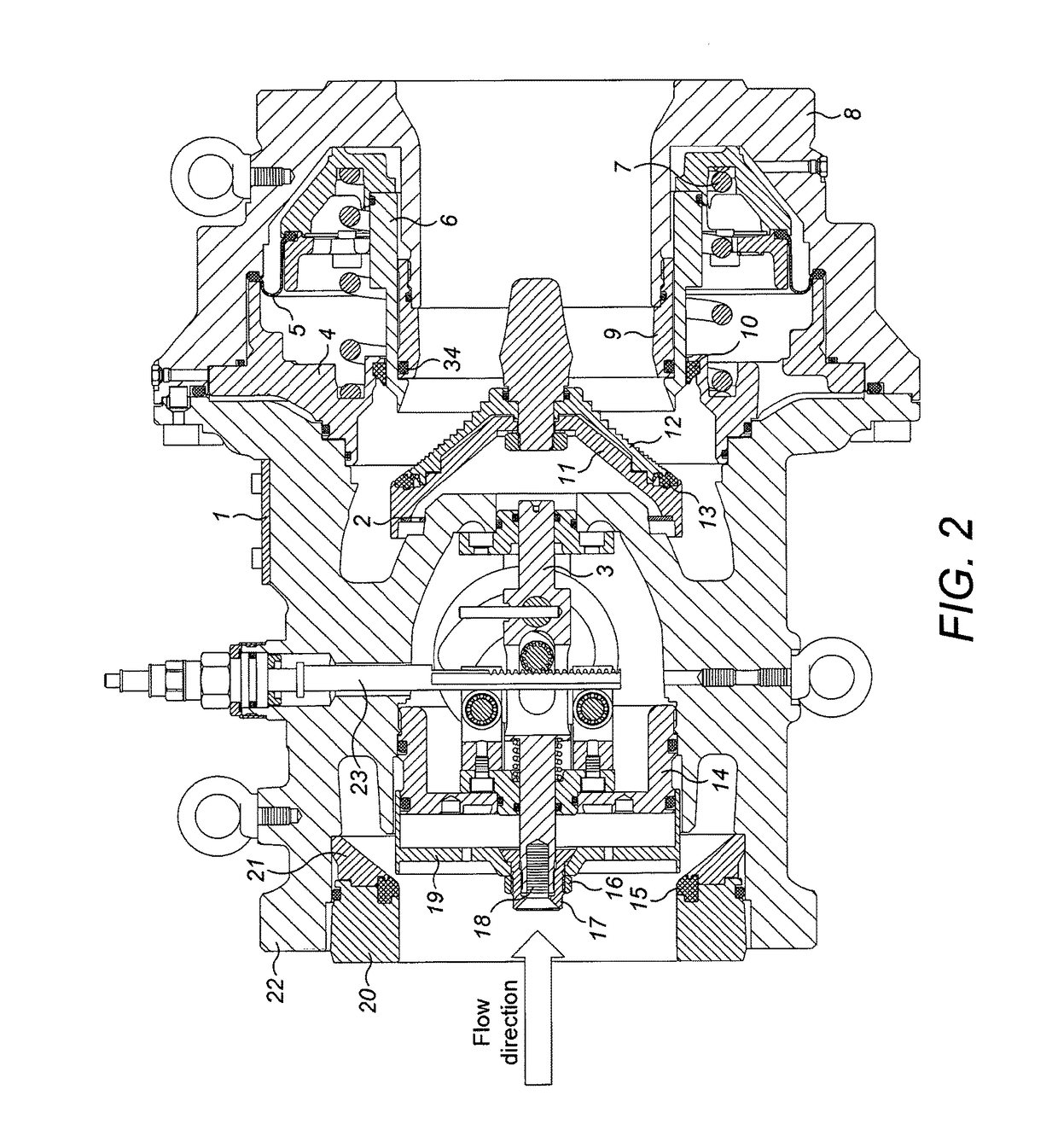
The patent describes a device that uses a compact design with a control valve plug and a regulator piston. This design has technical advantages such as reducing the size of the device and improving its performance.

Problems solved by technology

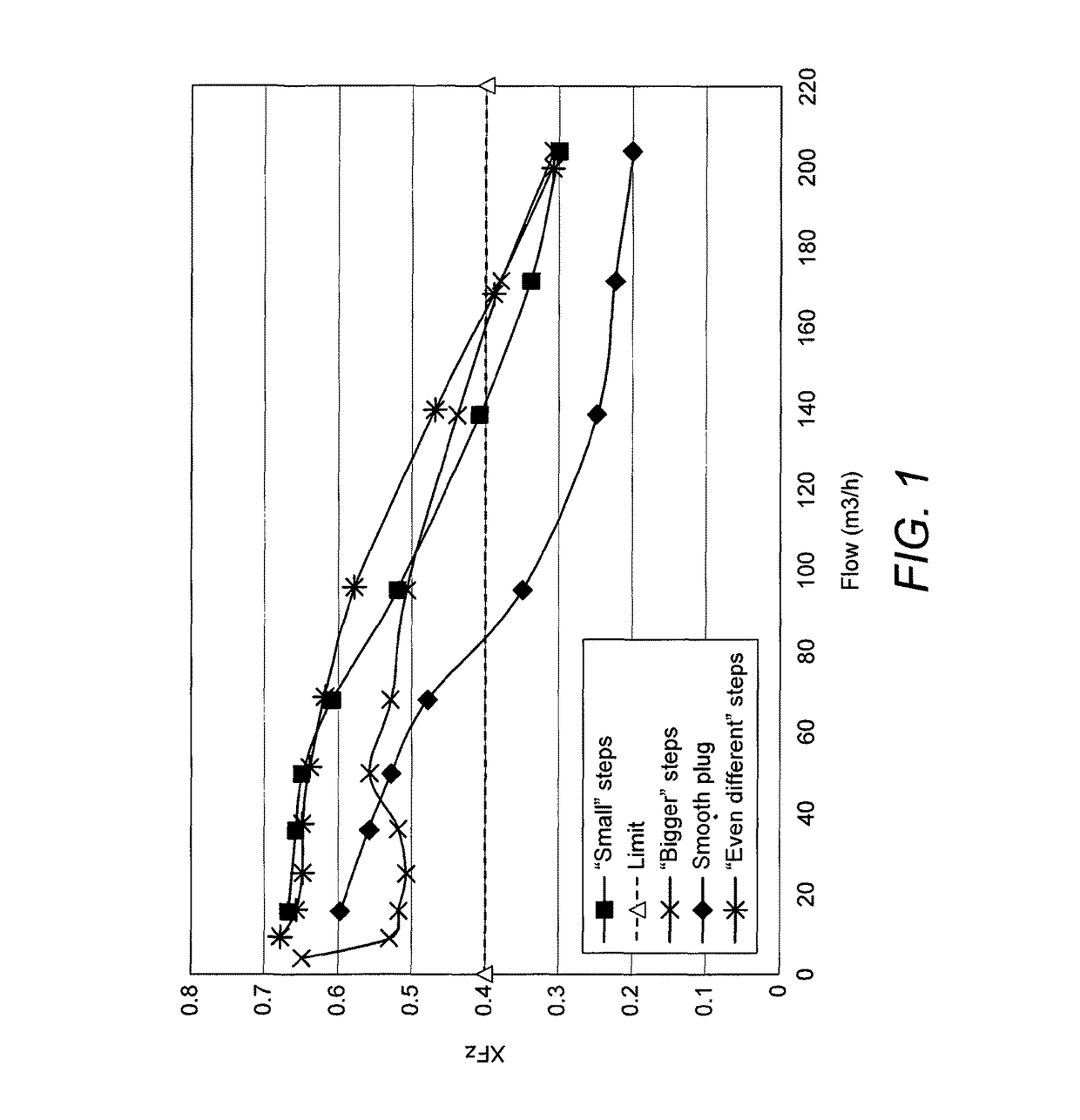
If the control valve is chosen with a maximum opening that is larger than the maximum needed for the application, then it must be controlled to close excessively at all times. This excessive closure results in unstable control as the control valve changes from an open condition to a closed condition repeatedly rather than settling at the proper location.
Conversely, if the valve is chosen with too small a maximum opening, excessive pumping energy is required to address unnecessary pressure drops arising in the system.
This problem is compounded by the fact that control valves are ordinarily available only in fixed steps, forcing the user to select one or another type of error.
An ordinary control valve provides no means for reading the flow rate of the fluid, nor of manually adjusting its maximum opening which will cause an ordinary control valve to incorrectly control the flow of fluid.
While the amount of surplus pressure might be calculated in theory, in practice the calculations are often not done due to their complexity, or are inaccurate due to construction variations.
The result can be that under different load conditions, the system uses more power than necessary, or some terminals do not get the amount of fluid they need, or the operation of some terminals is unstable.
The known valves suffer from the problem that the restriction created by the balancing valve is not taken into account by the control valve, so that a portion of the control valve's stroke is wasted.
A problem suffered by some prior art devices is that they are bulky, especially in large sizes.
A further problem suffered by prior art devices is that they do not have the correct relationship between their stem position and the heat transfer of the connected device, particularly when they are adjusted to a particular maximum flow.

Method used


Image

  • Pressure independent control and balancing valves
  • Pressure independent control and balancing valves
  • Pressure independent control and balancing valves

Examples


Embodiment Construction

[0074]It will be appreciated that aspects, embodiments and preferred features of the invention have been described herein in a way that allows the specification to be written in a clear and concise way. However, unless circumstances clearly dictate otherwise, aspects, embodiments and preferred features can be variously combined or separated in accordance with the invention. Thus, preferably, the invention provides a device having features of a combination of two or more, three or more, or four or more of the aspects described herein. In a preferred embodiment, a device in accordance with the invention comprises all aspects of the invention.

[0075]Within the context of this specification, the word “about” means plus or minus 20%, more preferably plus or minus 10%, even more preferably plus or minus 5%, most preferably plus or minus 2%.

[0076]Within the context of this specification, the word “comprises” means “includes, among other things” and should not be construed to mean “consists ...


PUM


Abstract

A device having pressure independent control and balancing valves, suitable for use in a hydronic system, comprises a seat, a plug having an upstream surface and a downstream surface, and a piston, wherein the seat, plug and piston are aligned coaxially, a controller determines the size of a first flow restriction between the upstream surface of the plug and the seat, the piston is operable to move in response to differential pressure across the first restriction and a predetermined force, the position of the piston relative to the downstream surface of the plug determining the size of a second flow restriction thereby in use maintaining a substantially constant differential pressure across the first restriction.

Description

Cross-Reference to Related Applications[0001]This application is a U.S. National Stage Filing of PCT Application No. PCT / EP2014 / 053539 filed on Feb. 24, 2014, and published in English as International Publication No. WO 2014 / 131727 A3 on Sep. 4, 2014, and claims priority of European Patent Application No. 13157343.8 filed on Feb. 28, 2013, the entirety of which are both hereby incorporated herein by reference.[0002]The present invention relates to a device having pressure independent control and balancing valves. Control valves and balancing valves are commonly used in hydronic systems to monitor and adjust fluid flow rate and ensure a relatively steady flow of fluid.BACKGROUND OF THE INVENTION[0003]In fluid networks, it is common to distribute fluid from a source to one or more points of consumption (loads). In order to provide the correct amount of fluid under varying demands, one or more control valves are commonly provided. These control valves respond to a control signal to cre...

Claims


Application Information

Patent Timeline
Patent Type & Authority Patents(United States)
IPC IPC(8): G05D7/01
CPCG05D7/014Y10T137/353
Inventor VOLOVEC, PETERLAH, SLAVKOBOZIC, GREGOR
Owner IMI HYDRONIC ENG INT SA
Learn More