Measuring device

a technology of measuring device and sensor section, which is applied in the field of measuring device, can solve problems such as achieve the effects of reducing damage to the sensor section, smooth dispersion, and improving resistance to external for

Pending Publication Date: 2022-03-24
MURATA MFG CO LTD
View PDF3 Cites 0 Cited by
  • Summary
  • Abstract
  • Description
  • Claims
  • Application Information

AI Technical Summary

Benefits of technology

[0008]Accordingly, it is an object of the exemplary embodiments of the present invention to provide a measuring device constructed with reduced occurrence of damage to a sensor section.
[0010]According to the configuration of the exemplary embodiment, because the via-hole conductors, where many interfaces of different kinds are present and the effect of deformation caused by the external force tends to concentrate on, are arranged in position corresponding to the tooth sections inside the region surrounded by the tooth sections on the opposite ends in the direction in which the plurality of tooth sections in the pair of comb electrodes are aligned and the connection sections in the pair of comb electrodes, the via-hole conductors are surrounded by the tooth sections and the connection sections. Thus, in comparison with the case where the positions of the via-hole conductors are set at the connection sections or the case where the they are set at the tooth sections on the opposite ends in the direction in which the plurality of tooth sections in the comb electrodes are aligned, the external force is more smoothly dispersed, and thus the external force acting on the comb electrodes can be released from the via-hole conductors. In particular, the technical advantage of resisting the external force is improved by placing the via-hole conductors in a relatively inner area (e.g., a central area), and thus damage to the sensor section is reduced.
[0011]The measuring device according to the exemplary embodiment of the present invention reduces the occurrence of damage to the sensor section.

Problems solved by technology

That operation and force may cause damage to the sensor section.

Method used


Image

  • Measuring device
  • Measuring device
  • Measuring device

Examples


first exemplary embodiment

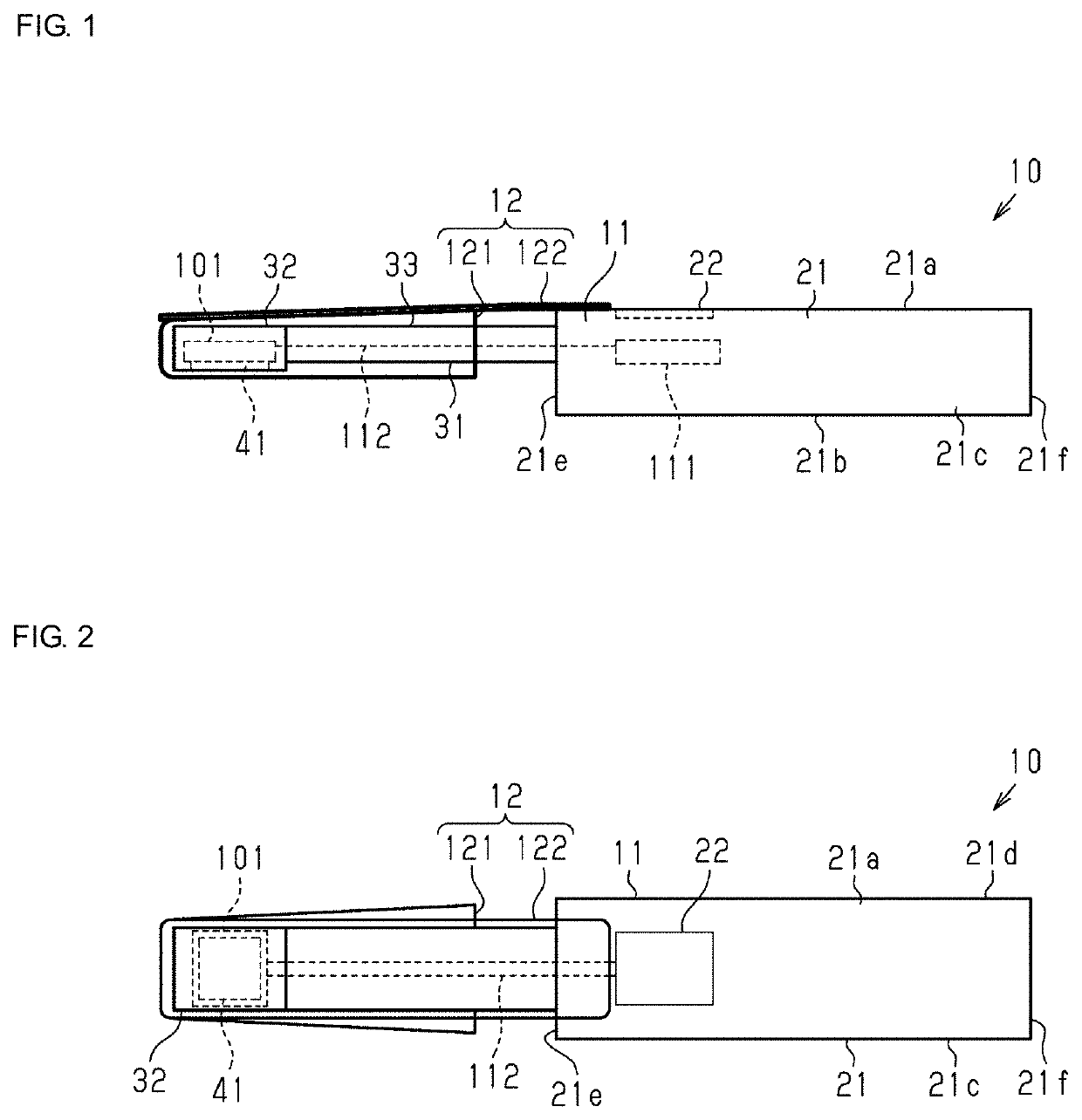
[0036]As illustrated in FIG. 1, a measuring device 10 includes a main body 11 and a cover 12 attached to the main body 11. Moreover, the measuring device 10 can be an oral cavity moisture measuring device for measuring the moisture content in an oral cavity as an example of a target for measurement.

[0037]As illustrated in FIGS. 1 and 2, the main body 11 includes a grip section 21 being a first end portion region (also referred to as a “first end”) of the main body 11 in the longitudinal direction and a probe section 31 being a second end portion region (also referred to as a “second end”) of the main body 11 in the longitudinal direction.

[0038]As shown, the grip section 21 (also referred to as a “grip”) has a substantially cuboid shape that is longer in the same direction as the longitudinal direction of the main body 11 and includes an upper surface 21a, a lower surface 21b, side surfaces 21c and 21d, and end surfaces 21e and 21f. In an exemplary aspect, a display section 22 (also ...


PUM

PropertyMeasurementUnit
thicknessaaaaaaaaaa
thicknessaaaaaaaaaa
thicknessaaaaaaaaaa

Abstract

A measuring device is provided for reducing the occurrence of damage to a sensor section. The sensor section includes a substrate, a pair of comb electrodes on a first principal surface, and a pair of back-side electrodes disposed on a second principal surface and corresponding to the pair of comb electrodes, respectively. The pair of comb electrodes includes a plurality of tooth sections and connection sections that connect the tooth sections to each other, respectively. The substrate includes via-hole conductors in positions corresponding to the tooth sections inside a region surrounded by the outer tooth sections on opposite ends in a direction in which the tooth sections in the pair of comb electrodes are aligned and the connection sections. The via-hole conductors connect the comb electrodes and the back-side electrodes.

Description

CROSS REFERENCE TO RELATED APPLICATIONS[0001]The present application is a continuation of PCT / JP2020 / 021677 filed Jun. 2, 2020, which claims priority to Japanese Patent Application No. 2019-106731, filed Jun. 7, 2019, the entire contents of each of which are incorporated herein by reference.TECHNICAL FIELD[0002]The present invention relates to a measuring device.BACKGROUND[0003]Patent Documents 1 and 2 (identified below) provide examples of measuring devices for measuring an object held by a hand of a measurer, and, more particularly, are examples of oral cavity moisture measuring devices. Such measuring devices include a capacitive sensor section at a leading end of a probe section that measures the moisture content of the object while a measurement surface of the sensor section is pressed to a surface to be measured of a tongue mucous membrane or the like, as the object.[0004]In one example, the sensor section in the measuring device in Patent Document 2 includes comb electrodes h...

Claims


Application Information

Patent Timeline
Patent Type & Authority Applications(United States)
IPC IPC(8): A61B5/0537G01N27/22A61B5/00
CPCA61B5/0537A61B2562/0209A61B5/682G01N27/223G01D11/24
Inventor TAKAGI, JUNTANAKA, KENJITAKAHASHI, TOMOKI
Owner MURATA MFG CO LTD
Why Eureka
Try Eureka