
Electric motor with outer radiator and two separate cooling circuits

a cooling circuit and motor technology, applied in the direction of dynamo-electric machines, electrical apparatus, magnetic circuit shapes/forms/construction, etc., can solve the problems of hammering the cooling efficiency of the primary cooling circuit of the stator, and achieve the effect of efficient and simple cooling of the stator

Active Publication Date: 2017-09-19
ALSTOM TRANSPORT TECH SAS
View PDF2 Cites 2 Cited by
  • Summary
  • Abstract
  • Description
  • Claims
  • Application Information

AI Technical Summary

Benefits of technology

The invention proposes an electric motor with cooling circuits that allow for efficient and simple cooling of both the stator and rotor. The primary cooling circuit cools the stator efficiently, which increases the motor's lifetime and allows it to operate at higher power. The secondary cooling circuit is also improved through the use of a second heat exchange area between the outside air and the gas fluid circulating in the secondary circuit. This results in better cooling performance.

Problems solved by technology

This crossing of both circuits hampers the cooling efficiency of the primary cooling circuit of the stator since the total volume of the primary cooling circuit has to be limited in order to let through the secondary cooling circuit.

Method used


Image

  • Electric motor with outer radiator and two separate cooling circuits
  • Electric motor with outer radiator and two separate cooling circuits

Examples


first embodiment

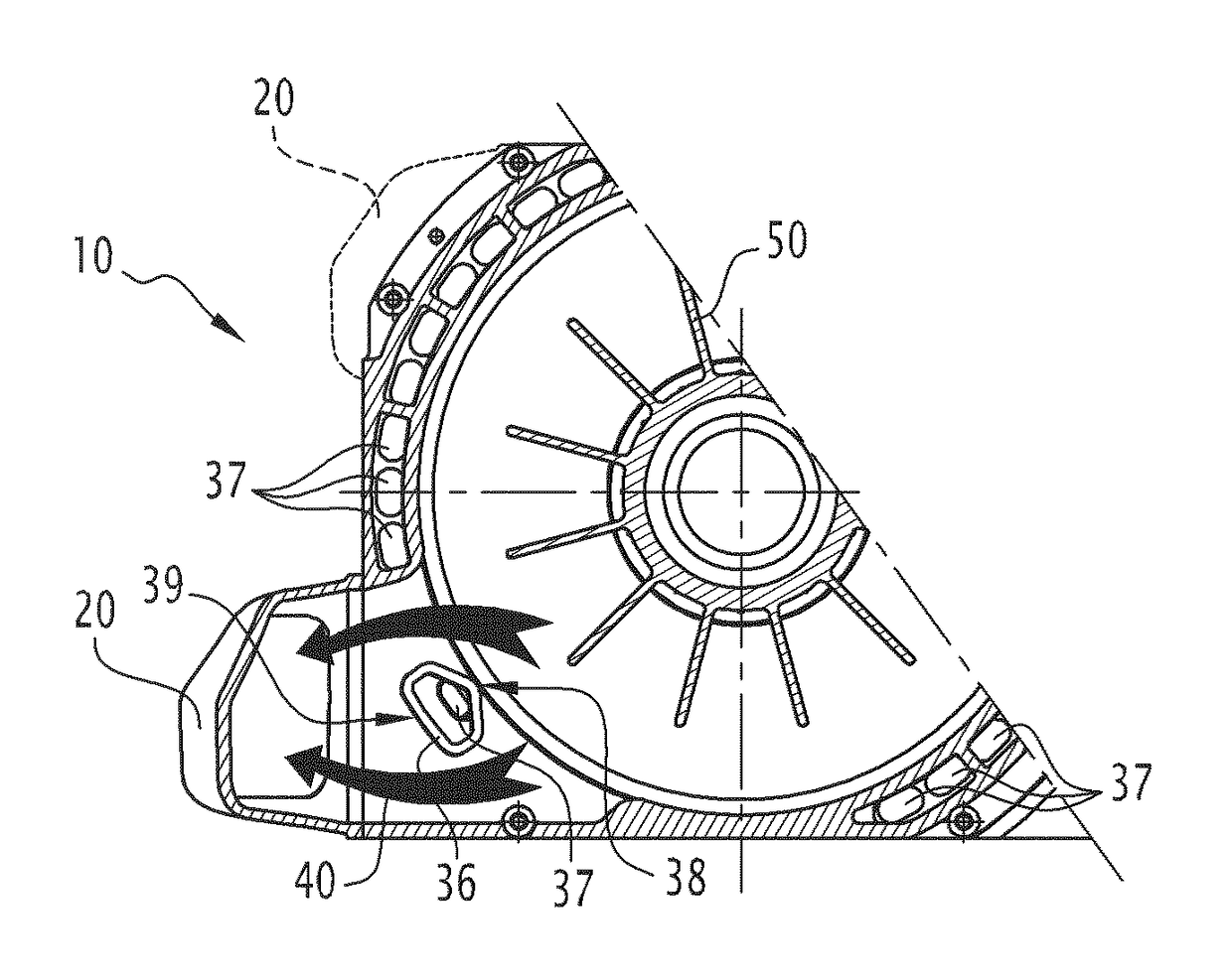
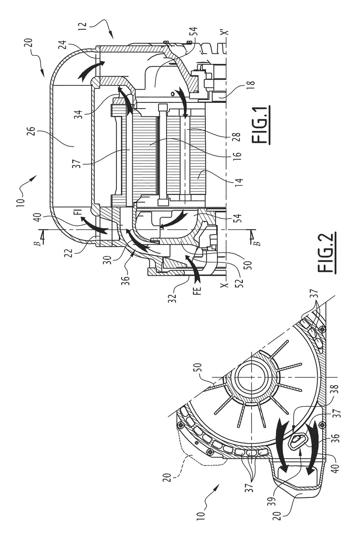
[0028]An electric motor 10 according to the invention is illustrated in FIGS. 1 and 2. The electric motor 10 comprises a frame 12 defining a volume internal to the motor 10 in which is housed a rotor 14 and a stator 16. The rotor 14 is mounted so as to rotate therewith on a rotational shaft 18 inside the frame 12 and mounted so as to be rotatable around an axis of rotation X-X′ relatively to the stator 16. The stator 16 surrounds the rotor 14 parallel to the axis of rotation X-X′ inside the frame 12. Conventionally, the rotor 14 and the stator 16 give the possibility of transforming electric energy into a mechanical energy delivered by the shaft 18 of the rotor 14.

[0029]According to an embodiment, a primary cooling circuit 30 includes a primary inlet 32 and a primary outlet 34, each being in fluidic communication with the outside of the frame 12. By this, it is meant that ambient air is able to penetrate into the primary cooling circuit 30 through the primary inlet 32 and to return ...

second embodiment

[0048]In a second embodiment, several cooling devices 20 are arranged around the frame 12 of the motor 10 (see FIG. 2). Each cooling device 20 is in fluidic communication with said or one secondary cooling circuit 40. All the secondary cooling circuits 40 cross the rotor 14 of the motor 10. Thus, the cooling of the motor 10, in particular of the rotor 14, is increased. This gives the possibility of increasing the performance level of the motor 10, while guaranteeing optimum, efficient and simple cooling.

[0049]The total cooling of the motor 10 produced by the primary cooling circuit 30 and by the secondary cooling circuit 40 has at least a power of 12 kW.

[0050]The mechanical power delivered by the shaft 18 of the motor 10 is of at least 400 kW.


PUM


Abstract

A motor includes a frame defining an internal volume in which are housed a rotor and a stator; at least one cooling circuit, which includes a primary inlet and a primary outlet in fluidic communication with the outside of the frame; at least one cooling device outside the frame, which includes a secondary air inlet and a secondary air outlet, and a conduit; at least one secondary cooling circuit, separate from the primary circuit, crossing the rotor and in fluidic communication with the secondary inlet and the secondary outlet of the cooling device. The secondary cooling circuit is crossed by a channel of the primary cooling circuit supplying the stator with the gas fluid from the outside of the frame.

Description

CROSS-REFERENCE TO RELATED APPLICATION[0001]This application claims priority to French Patent Application No. 15 50941 filed on Feb. 6, 2015, the disclosure of which including the specification, the drawings, and the claims is hereby incorporated by reference in its entirety.FIELD OF THE INVENTION[0002]The present invention relates to an electric motor, including a primary cooling circuit for cooling a stator and a secondary cooling circuit for cooling a rotor.BACKGROUND OF THE INVENTION[0003]Usually, the primary cooling circuit is in fluidic communication with the outside of the frame of the motor so as to allow cooling of the stator by having ambient air circulate in the primary cooling circuit. Generally, the secondary circuit is, as for it not in fluidic communication with the outside of the frame of the electric motor in order to avoid that dust or other materials jam or foul the mobile portion of the motor. Consequently, the secondary circuit is connected to a cooling device e...

Claims


Application Information

Patent Timeline
Patent Type & Authority Patents(United States)
IPC IPC(8): H02K9/18H02K1/20H02K9/06
CPCH02K9/06H02K1/20H02K9/18H02K9/14
Inventor RANDRIA, ANDRYRAGUIN, BRUNO
Owner ALSTOM TRANSPORT TECH SAS
Learn More