Camera module with adhesive groove

a technology of adhesive grooves and camera modules, applied in the field of camera modules, can solve problems such as the removal of magnets from the housing, and achieve the effects of facilitating assembly of camera modules, enhancing adhesive strength, and preventing the removal of magnets at the housing

Active Publication Date: 2017-09-19
LG INNOTEK CO LTD
View PDF3 Cites 2 Cited by
  • Summary
  • Abstract
  • Description
  • Claims
  • Application Information

AI Technical Summary

Benefits of technology

[0011]In order to solve out the aforementioned problem of the conventional camera module, one purpose of the present disclosure is to provide a camera module where the magnet may be stably accommodated in the housing.
[0012]Another purpose of the present disclosure is to provide a camera module capable of preventing removal of the magnet even when the camera is shocked by an external impact such as dropping down.
[0013]Still another purpose of the present disclosure is to provide a camera module including a magnet removal prevention portion for preventing the magnet from being removed off when external force is applied to the camera module.
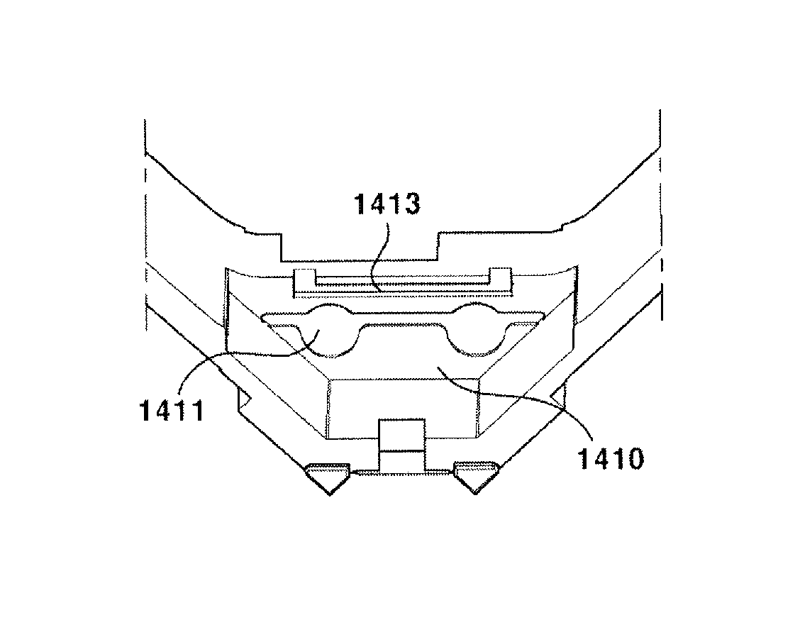
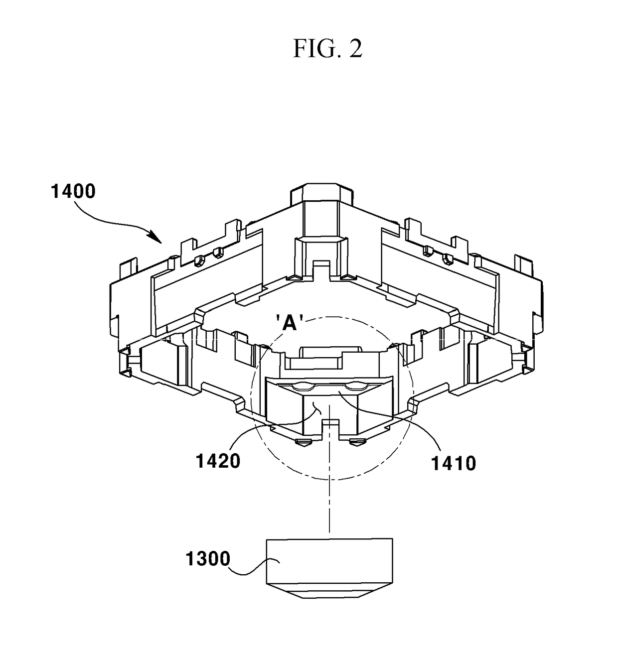
[0035]In addition, the first adhesive groove accommodating an adhesive as well as the second or complemental adhesive groove may be formed at a lower surface of the rib of the housing, to fill up an adhesive and adhere the magnet on a lower surface of the rib. Thereby, the adhesive strength may be enhanced, and departure of the magnet arranged at the housing may be prevented, even when the camera is shocked by an external impact such as dropping down. Accordingly, the assembly of camera modules may be facilitated and stability of the camera in operation may be enhanced.
[0036]In addition, an adhesive may be injected into an opening of the complemental adhesive groove formed on a side surface of the rib, and the amount of the injected adhesive may be ascertained through another opening with the naked eye. Therefore, the adhesive may be prevented from being overflowing in the adhesive groove and flowing in the camera module, and accordingly, defect rate in operation of the camera module may be decreased.
[0037]According to an exemplary embodiment of the present disclosure, the magnet may be prevented from being removed from the magnet accommodating portion of the housing even when external force is applied to the camera module.

Problems solved by technology

However, the conventional camera module as described in the above has a problem in that the magnet is removed from the housing through the open surface of the housing when external force is applied to the camera module.

Method used


Image

  • Camera module with adhesive groove
  • Camera module with adhesive groove
  • Camera module with adhesive groove

Examples


Embodiment Construction

[0053]Hereinafter, exemplary embodiments of the present disclosure will be described with reference to the exemplary drawings. In designating elements in the drawings as reference numerals, wherever possible, the same reference numerals are used to refer to the same element, even though the same elements are illustrated in different drawings. In addition, in describing exemplary embodiments of the present disclosure, when it is determined that a detailed description about known function or structure relating to the present disclosure may disturb understanding of exemplary embodiments of the present disclosure, the detailed description may be omitted.

[0054]In addition, in describing elements of exemplary embodiments of the present disclosure, the terms such as “first”, “second”“A”, “B”, “(a)” and “(b)” may be used. However, such terms are used merely to distinguish a particular element from another element, and therefore, essence, order or sequence of the relevant elements shall not ...


PUM


Abstract

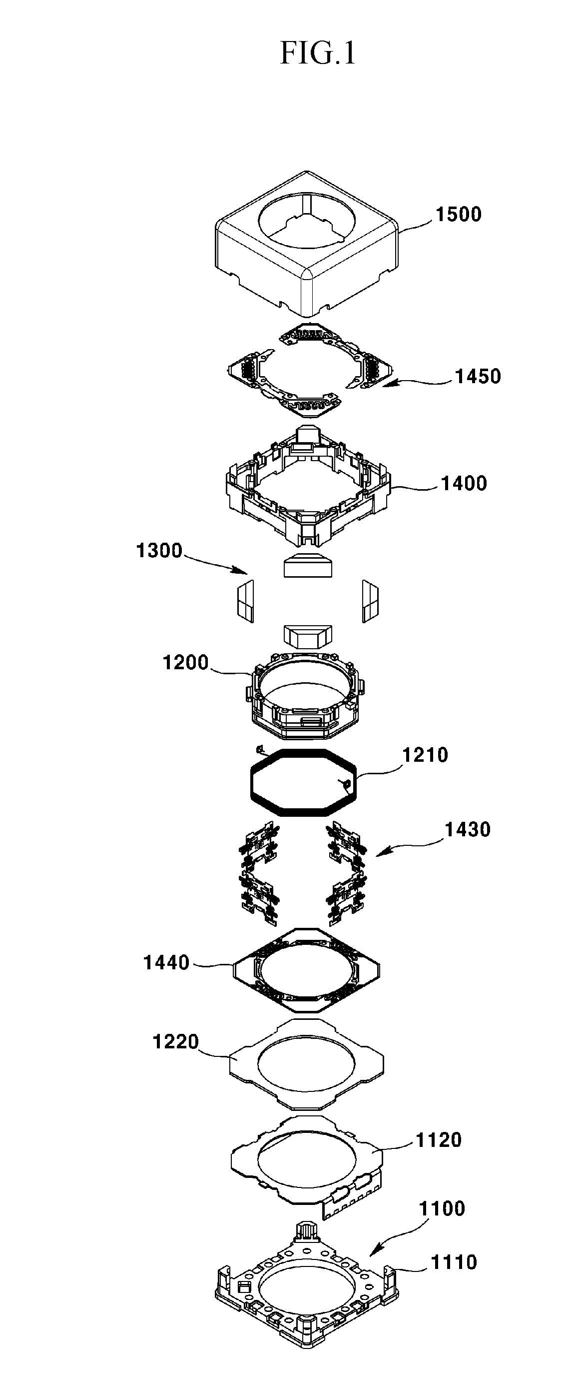
A camera module is provided, the camera module comprising: a bobbin; a coil arranged at the bobbin; a housing disposed at an inside of the bobbin; a magnet arranged at the housing, to face the bobbin; a rib formed at an inside to be extended from a first lateral wall of the housing to a second lateral wall adjacent to the first lateral wall; and a first adhesive groove formed by a part of a lower surface of the rib being recessed to accommodate an adhesive. The camera module has an advantageous effect in that the magnet may be prevented from being removed from the magnet accommodating portion of the housing, even when external force is applied to the camera module.

Description

CROSS-REFERENCE TO RELATED APPLICATIONS[0001]This application claims the benefit under 35 U.S.C. §119 of Korean Application No. 10-2014-0182667 filed Dec. 17, 2014, and of Korean Patent Application No. 10-2014-0188416 filed Dec. 24, 2014, which are hereby incorporated by reference in their entirety.BACKGROUND[0002]Field of the Invention[0003]The present disclosure relates to a camera module.[0004]Background of the Related Art[0005]The technology described in this section is merely intended to provide background information of an exemplary embodiment of the present disclosure, and does not mean the prior art.[0006]Concomitant with wide propagation of various mobile terminals and commercialization of wireless Internet services, demands by consumers related to the mobile terminals are diversified, and various types of additional equipment are attached to the mobile terminals.[0007]Among the various types of additional equipment, a camera module may be a representative device capable of...

Claims


Application Information

Patent Timeline
Patent Type & Authority Patents(United States)
IPC IPC(8): H04N5/225H04N5/232
CPCH04N5/2252H04N5/2257H04N5/23212H04N23/51H04N23/50H04N23/54H04N23/55H04N23/57
Inventor CHO, JAE HONGLEE, HEE SEHAN, JIN SUK
Owner LG INNOTEK CO LTD
Why Eureka
Try Eureka