
Mixing device and turbofan engine having such mixing device

a technology of mixing device and turbofan engine, which is applied in the direction of machine/engine, engine manufacturing, jet propulsion plant, etc., can solve the problems of limited deflection direction of these mixing devices, and achieve the effect of small radial structural spa

Inactive Publication Date: 2017-09-26
MTU AERO ENGINES GMBH
View PDF6 Cites 0 Cited by
  • Summary
  • Abstract
  • Description
  • Claims
  • Application Information

AI Technical Summary

Benefits of technology

The patent describes a way to design an actuating device for pivoting walls that is both compact and sturdy. This is achieved by making the first and second positions of the device radially distanced from each other, but still able to pivot the walls. Additionally, a support structure is provided that is disposed adjacent to the walls, which makes it simple to establish the axial position of the adjusting ring. The technical effects of this invention are a more efficient use of space and a simplified and robust actuating device for pivoting walls.

Problems solved by technology

The direction of deflection, however, is limited in these mixing devices by the elasticity of the material.

Method used


Image

  • Mixing device and turbofan engine having such mixing device
  • Mixing device and turbofan engine having such mixing device
  • Mixing device and turbofan engine having such mixing device

Examples


Embodiment Construction

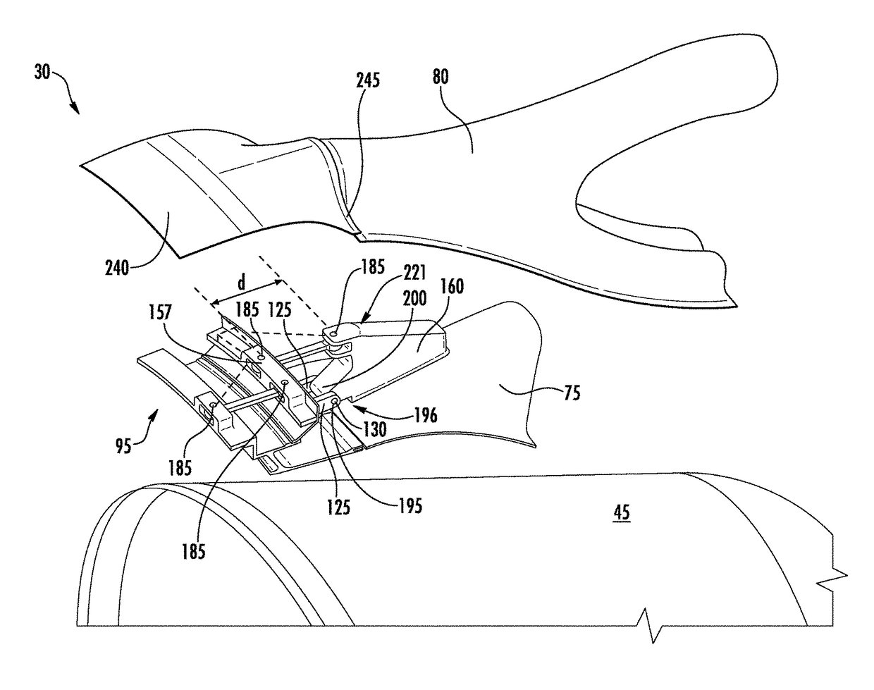
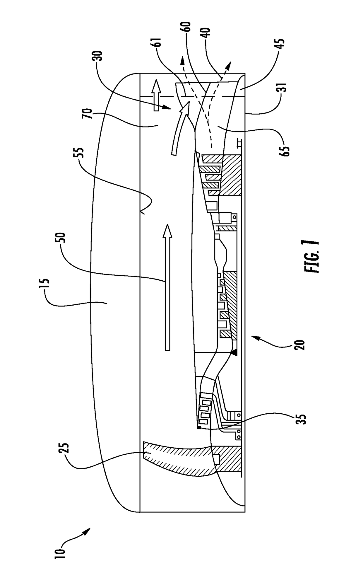
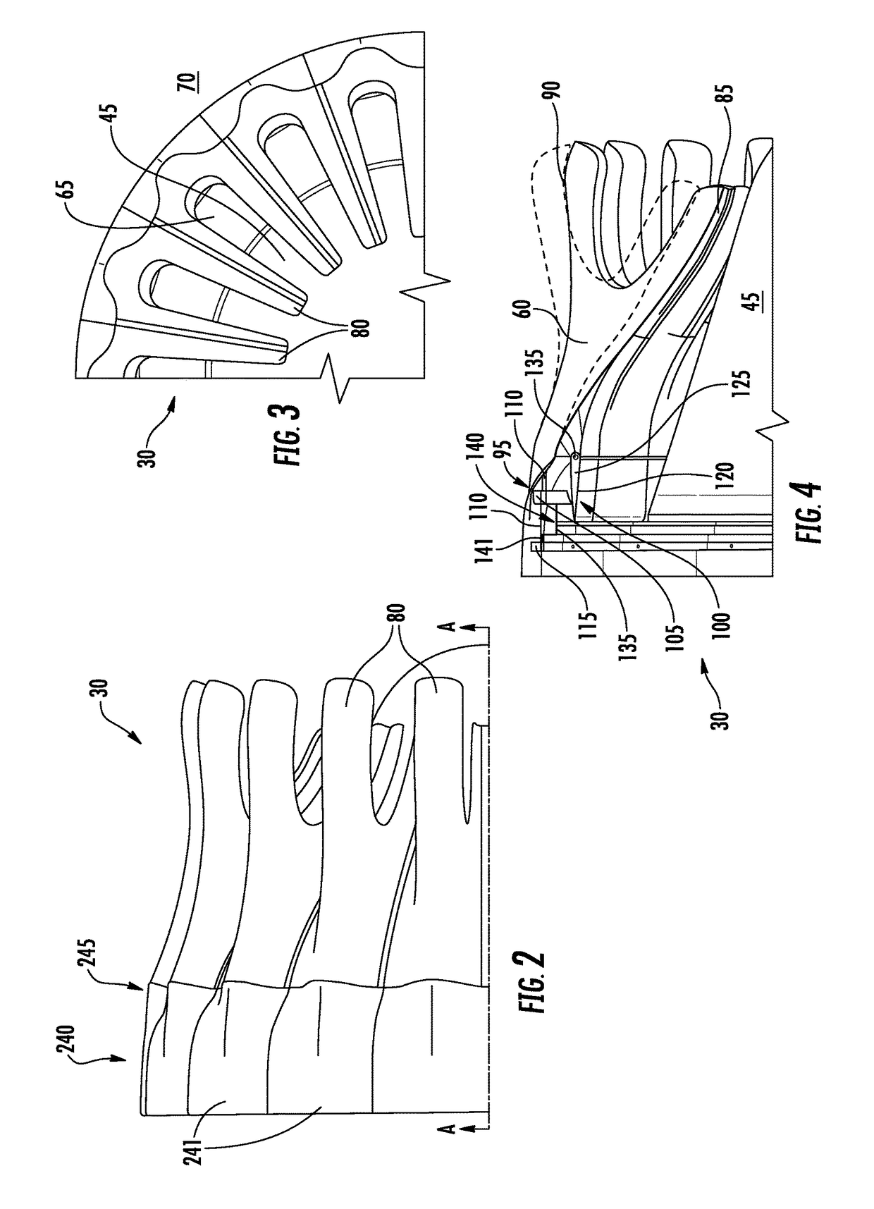
[0023]FIG. 1 shows a schematic sectional view through a turbofan engine 10 having a mixing device 30.

[0024]The turbofan engine 10 is disposed in an engine nacelle 15 and comprises an aircraft gas turbine 20, a fan 25, which is arranged on the upstream side relative to the aircraft gas turbine 20, as well as the mixing device 30 arranged on the downstream side relative to the aircraft gas turbine 20. Further, elements of the aircraft gas turbine 20 and of fan 25 are disposed rotatable around an axis of rotation 31 of the turbofan engine 10. During operation of the turbofan engine 10, an air flow that is produced is divided at a flow splitter 35. A portion of the air flow that flows radially inside, also called the core or primary flow, is guided through the aircraft gas turbine 20 and leaves the aircraft gas turbine 20 on the downstream side as hot-air flow 40 (dashed line) between an exhaust gas cone 45 and the mixing device 30. A flow of cold gas 50 (solid line) running radially ou...


PUM


Abstract

The invention relates to a mixing device and a turbofan engine having such a mixing device 30 for mixing a first gas flow 40 with a second gas flow 50 in a turbofan engine 20, having an actuating device 95 and walls 60, which bound a channel 65 for the first gas flow 40 and a channel 70 lying radially outside for the second gas flow 50, the actuating device 95 comprising a coupling element 110 that is coupled to the walls (60), the actuating device 95 being designed to pivot the walls 60 between a first position and a second position disposed radially outside relative to the first position, the actuating device 95 comprising an adjusting ring 105 that can be rotated between a first rotating position and a second rotating position in the peripheral direction and that is joined to the coupling element 110.

Description

BACKGROUND OF THE INVENTION[0001]The invention relates to a mixing device for mixing a first gas flow with a second gas flow in a turbofan engine, having an actuating device and walls that bound a radially inner-lying channel for the first gas flow and a radially outer-lying channel for the second gas flow, the actuating device comprising a coupling element that is coupled to the walls, the actuating device being designed to pivot the walls from a first position to a second position disposed radially outside relative to the first position by means of the coupling element.[0002]In turbofan engines, a noise reduction and a reduction of specific fuel consumption can be achieved by mixing a mantle flow of a fan and a core flow of an aircraft gas turbine. Conventionally, mixing takes place via a mixing device having a meandering profile that is positioned downstream behind a low-pressure turbine of the aircraft gas turbine, this mixing device alternately deflecting at least one partial f...

Claims


Application Information

Patent Timeline
Patent Type & Authority Patents(United States)
IPC IPC(8): F02K3/075F02K1/38F02K1/48F02K1/46F02K1/06
CPCF02K3/075F02K1/386F02K1/06F02K1/46F02K1/48F05D2250/61
Inventor KLINGELS, HERMANNKLAEN, STEPHANSCHERER, CHRISTIANVOGEL, UWE
Owner MTU AERO ENGINES GMBH
Learn More