Laser diode arrangement with external resonator

a laser diode and external resonator technology, applied in the direction of optical resonator shape and construction, laser details, electrical apparatus, etc., can solve the problems of insufficient compensation of contributions of the second or higher order of chromatic dispersion, fluctuation of output power of the laser diode, and detrimentally affecting spectroscopic examination procedures. , to achieve the effect of avoiding light output and mode hops in the spectral tuning curve of the laser system,

Inactive Publication Date: 2005-05-19
SACHER JOACHIM
View PDF3 Cites 10 Cited by
  • Summary
  • Abstract
  • Description
  • Claims
  • Application Information

AI Technical Summary

Benefits of technology

[0019] In a further embodiment the laser diode is a quantum cascade laser which permits the utilization of differently arranged wavelength ranges. It is an important feature of the invention that the laser radiation can be uncoupled by way of the rear facet of the laser diode, wherein the ratio of the reflectivity of the rear facet to the reflectivity of the optical reflection element is much smaller than 1. In this way, a much greater power can be uncoupled from the laser diode arrangement. At the same time, variations in the light output and mode hops in the spectral tuning curve of the laser system are effectively avoided. This is particularly true if the ratio of the reflectivity of the rear facet to the reflectivity of the optical reflection element is smaller than 0.1. Preferably, the reflectivity of the rear facet is not more than 1% and the reflectivity of the optical reflection element is at least 95%.
[0020] The laser diode has preferably a length in axial direction of at least 500 μm which also results in a noticeable increase of the power that can be coupled. At the same time, the line width of the emitted laser radiation is reduced.

Problems solved by technology

Also, the output power of the laser diode fluctuates which detrimentally affects spectroscopic examination procedures.
Further control or adjustment means are not provided so that contributions of the second or higher order of the chromatic dispersion are not necessarily compensated for.
In addition, the not disappearing reflectivity of the laser diode facets facing the external resonator remains neglected so that, during tuning of the wavelength, power variations and mode hops can still occur.

Method used


Image

  • Laser diode arrangement with external resonator
  • Laser diode arrangement with external resonator
  • Laser diode arrangement with external resonator

Examples


Embodiment Construction

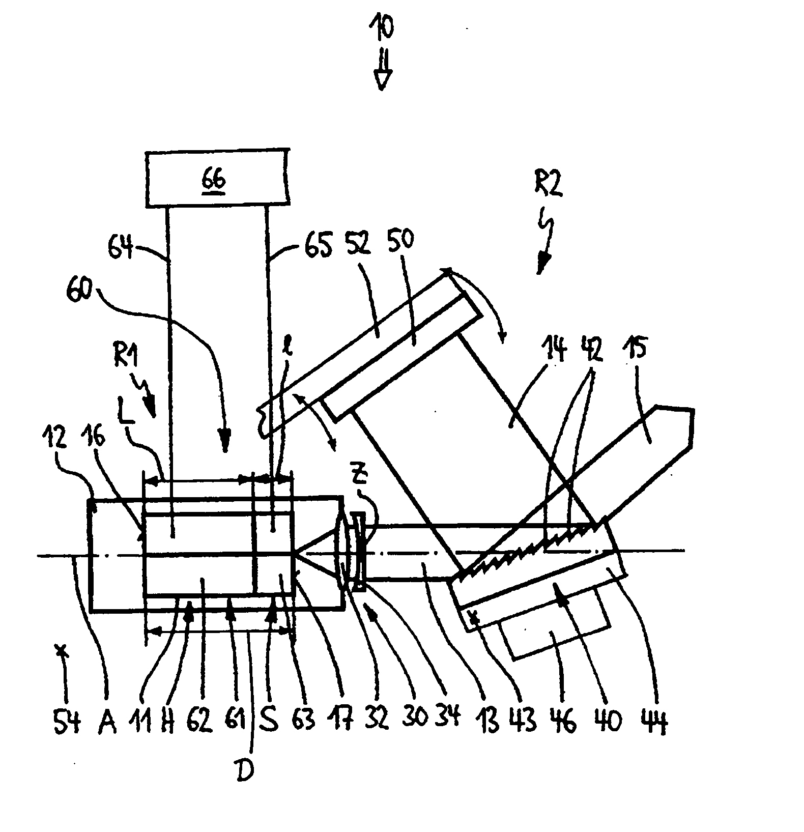
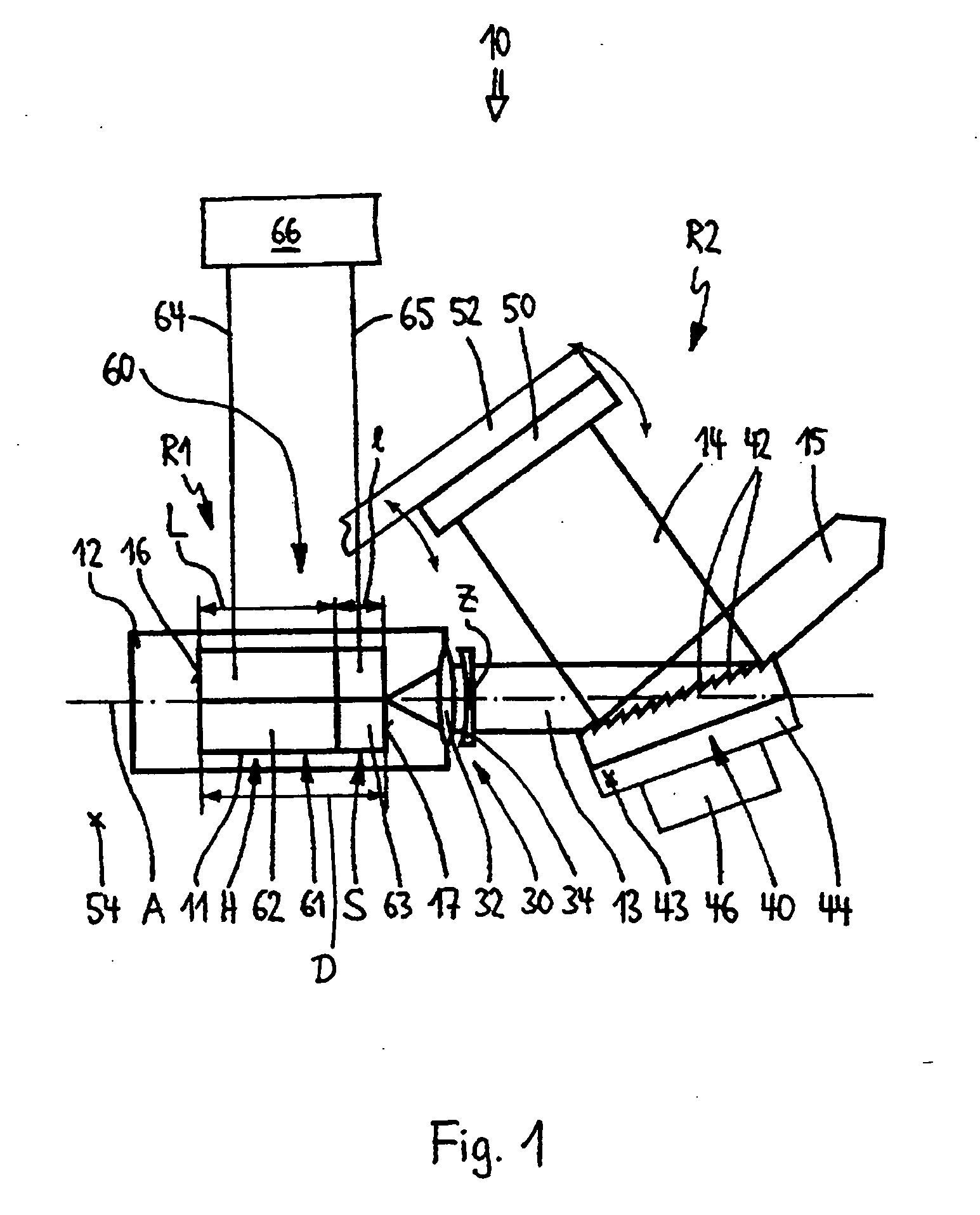
[0033]FIG. 1 shows laser diode arrangement 10 for generating single mode tunable laser radiation 15 in a Littman arrangement. It comprises a semiconductor laser diode 11, which is mounted on a carrier 12 such as a base plate or a mounting block. The rear facet 16 of the laser diode 11 is provided with a mirror surface having a reflectivity of almost 100%. The front facet 17 in contrast is provided with an antireflection coating whose reflectivity is less than 0.1%. Both facets 16, 17 form the end faces of a first resonator R1 whose length is determined by the length D of the semiconductor crystal of the laser diode 11.

[0034] The laser light 13 emitted from the laser facet 17 is focused by an optical transmission component 30 in the form of a rotational symmetrical collimation lens 32 onto the surface of an optical diffraction grating 40, which, as wavelength-selective reflection element, is, together with a mirror 50, part of an external resonator R2. The reflectivity of the planar...


PUM


Abstract

In a laser diode arrangement for generating single mode tunable laser radiation wherein the laser diode forms a first resonator and has rear and front facets and a second external resonator is coupled to the first resonator, and an optical transmission component and a wavelength selective optical reflection element are arranged in the laser light path from the laser diode for directing part of the laser light into the external resonator and coupling it back into the first resonator, means are provided for changing the coupling quality of the first resonator to the external, second resonator.

Description

BACKGROUND OF THE INVENTION [0001] The invention relates to a laser diode arrangement with an external resonator for the generation of single mode tunable laser radiation with a laser diode which forms a resonator. [0002] By means of a semiconductor laser diode which is operated in the flow direction, coherent light can be generated by stimulated emission. Because of the quality of the resonator formed between the end faces of the semiconductor crystal and because of the spontaneous emission within the laser diode however the emitted light has usually a relatively large line width. In order to reduce the line width generally an external resonator is used, which, by way of wavelength selective elements such as screens and filters, couples only light of certain wavelengths—the resonator modes—back into the laser diode. This results in an amplification of the stimulated emission based on a respective selected wavelength. At the same time, by way of the wave-length selective element, th...

Claims


Application Information

Patent Timeline
Patent Type & Authority Applications(United States)
IPC IPC(8): H01S5/0625H01S5/0683H01S5/14
CPCH01S5/06255H01S5/143H01S5/141H01S5/0683
Inventor SACHER, JOACHIM
Owner SACHER JOACHIM
Why Eureka
Try Eureka