Pump devices

a technology of pump and rotor, which is applied in the direction of rotary/oscillating piston pump components, machines/engines, liquid fuel engines, etc., can solve the problems of clogging the recirculation path, affecting the efficiency of pump operation, and the axial length and weight of magnetically driven pumps are greater, so as to achieve less expensive power ends and facilitate utilization. , the effect of compact rotor assembly design

Active Publication Date: 2018-03-20
PEOPLEFLO MFG
View PDF78 Cites 3 Cited by
  • Summary
  • Abstract
  • Description
  • Claims
  • Application Information

AI Technical Summary

Benefits of technology

[0011]In a first aspect, the present disclosure provides a magnetically driven pump having a compact advantageous design that overcomes the above discussed disadvantages associated with having radial and axial bearing surfaces well forward or rearward of the pumping area of a rotor assembly. The disclosure provides a magnetically driven pump that includes a casing, a rotor assembly, an inner magnet assembly and a canister assembly. The casing has a front portion, a rear portion, a discharge port and an inlet port. The rotor assembly includes a rear cylindrical opening having an inner wall surface and having a plurality of magnet segments connected to the inner wall surface, a front cylindrical opening having an inner wall surface that provides a radial bearing surface, and a first axial bearing surface. The canister assembly includes a cylindrical portion disposed within a radial gap between magnet segments of the inner magnet assembly and magnet segments of the rotor assembly, and a front portion extending from the cylindrical portion and having a radial bearing surface and a first axial bearing surface. In this design, the radial bearing surface of the rotor assembly and the radial bearing surface of the canister assembly front portion restrict radial motion of the rotor assembly, and the first axial bearing surface of the rotor assembly and the first axial bearing surface of the canister assembly front portion restrict forward motion of the rotor assembly.
[0013]In a third aspect, the present disclosure also addresses the lack of magnetically driven pumps able to meet the industry standards ASME B73.1 and / or ISO 5199 for mounting locations of key features and able to utilize the rear end mechanical drive portion commonly used with dynamically sealed pumps that meet the standard. The disclosure provides a magnetically driven rotodynamic pump that includes a stationary casing, an inner magnet assembly, and an impeller assembly. The stationary casing includes a discharge port, an inlet port, a mounting foot and a rear mounting flange. The inner magnet assembly has an inner ring and a plurality of magnet segment. The casing, inner magnet assembly and impeller assembly are configured and dimensioned to be assembled to a power end and adapter of a commercially available non-magnetically driven rotodynamic pump having a dynamic seal that is designed in accordance with dimensions specified in a pump industry standard, such that when assembled, the sizes and locations of the casing discharge port, the casing inlet port, the casing mounting foot, and the power end and adapter all meet the dimensions specified in the standard. The unique, axially compact design of a pump of the present disclosure is capable of utilizing the rear end mechanical drive components or power end normally in place for such centrifugal dynamically sealed pumps. Thus, the pump may be installed without needing to remove the power end that is connected to the electric drive motor, and therefore, without disturbing the electric motor and its mounting and electrical connections, and without disturbing the shaft alignment between the electric motor and the power end. Also, the new pump advantageously may be connected to existing power end and adaptor structures. This can be particularly beneficial to manufacturers that already make the power end and adapter components for the centrifugal dynamically sealed pumps. Moreover, it permits utilization of the less expensive power ends normally used with dynamically sealed pumps, and provides an opportunity for field retrofits that can be achieved by leaving in place the existing power end and only changing out the pump, while also gaining the advantages of a magnetically driven pump.
[0014]In a fourth aspect, the present disclosure addresses the previously noted issue that typical magnetically driven rotodynamic pumps having a front axial bearing at a nose cap must balance the benefit of having a small diameter at the center starting portion of the impeller vanes against the benefit of having a large diameter canister nose cap for the front axial bearing. The disclosure provides a magnetically driven rotodynamic pump having a stationary casing, a stationary canister assembly, and a rotatable rotor assembly. The stationary casing has a front portion, a rear portion, a discharge port and an inlet port. The stationary canister assembly is connected to the stationary casing. The stationary canister assembly further includes a canister and a stationary nose cap is connected to the canister and has an outer diameter, a rear axial bearing surface and a front surface. The rotatable rotor assembly includes an impeller having a plurality of front vanes, wherein a portion of the impeller front vanes extend forward of the nose cap front surface and inward to an inner diameter that is smaller than the outer diameter of the nose cap. Thus, the design includes the benefits of both a smaller diameter at the center starting portion of the impeller vanes and a large diameter canister nose cap having a front axial bearing. In this design, the stationary front surface of the nose cap is positioned where there would otherwise be an impeller base surface and the forward extending portions of the impeller vanes extend forward of the surface of the base of the impeller. This results in an advantageous relatively small diameter of the center starting ends of the impeller vanes combined with an advantageous relatively large outer diameter of the axial bearing at the nose cap of the canister assembly.
[0015]In a fifth aspect, the present disclosure provides a pump that includes a stationary casing having a front portion, a rear portion, a discharge port and an inlet port, and further includes a rotor assembly having a bushing wherein the bushing is of single piece construction and includes a radial bearing surface that restricts radial motion of the rotor assembly, a front axial bearing surface that restricts forward motion of the rotor assembly, and a rear axial bearing surface that restricts rearward motion of the rotor assembly. This design is believed to provide the first instance of a pump having a bushing for a rotor assembly that is of single piece construction while providing radial and front and rear axial bearing surfaces. This provides a particularly compact rotor assembly design.
[0016]In an sixth aspect, the present disclosure provides a pump that includes a stationary casing having a front portion, a rear portion, a discharge port and an inlet port, and further includes a rotor assembly having a rotor that includes a central opening extending axially through the rotor and having a step proximate one end of the central opening, a rotor ring, and a bushing, wherein the bushing fits inside the rotor central opening and is held in place between the rotor ring and the step in the central opening of the rotor. This design provides a uniquely compact and efficient bushing design and construction for a rotor assembly wherein a bushing extends through a portion of and is held within the rotor assembly by a fastening means at one end of the rotor assembly. This also enables the use of advantageous longer bearing surfaces.

Problems solved by technology

This results in a disadvantage of causing magnetically driven pumps to have greater axial length and weight, because the bearing support is located forward and / or rearward of the pumping portion of the rotor assembly.
The downside of a hole thru a single part is that it is prone to causing clogging of the recirculation path.
There are far fewer magnetically coupled pumps, so the power ends for magnetically driven pumps tend to be more costly.
Also, due to overall size and especially axial length, no magnetically coupled pumps known to the inventors have been able to utilize the power end that is commonly used with the dynamically sealed pumps while meeting either of the standards for the location of the stated features involved in mounting such pumps.
This requires a disadvantageous tradeoff pitting a desired small diameter for the front end of the impeller vanes against a desired large diameter of a front axial bearing.
This tends to add undesirable complexity and length to a pump.

Method used


Image

  • Pump devices
  • Pump devices
  • Pump devices

Examples


Embodiment Construction

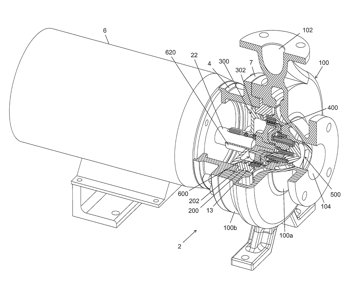
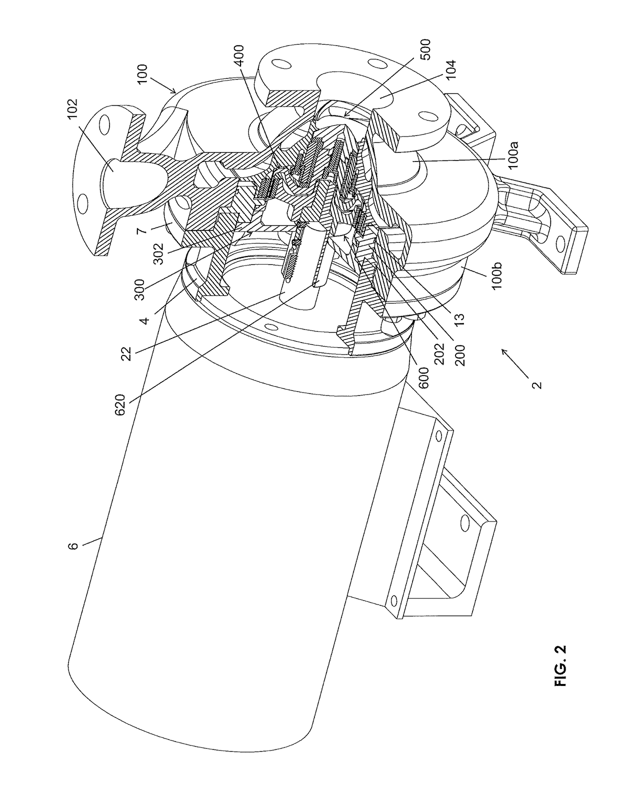
[0041]Referring generally to FIGS. 1-21, it will be appreciated that pumps devices of the present disclosure generally may be embodied within numerous configurations. Indeed, the teachings within this disclosure may pertain to dynamically sealed pumps, whether of the rotodynamic or positive-displacement types, and / or to magnetically driven or sealless pumps, whether of the rotodynamic or positive-displacement types. If of the magnetically driven type, the pumps may be of the inner magnet drive and / or outer magnet drive types.

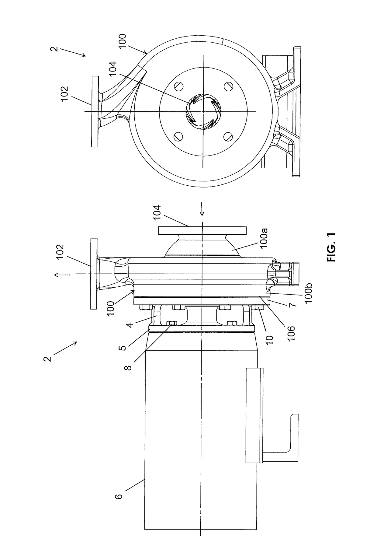
[0042]Referring to a preferred first example embodiment, in FIGS. 1-10, and particularly to FIGS. 1 and 2, an example pump 2 is shown connected to a motor adapter 4 that, in turn, is connected to a standard C-face electric motor 6. The configuration of pump 2 happens to be a magnetically driven rotodynamic pump. More particularly, a first flange 5 of the adapter 4 is connected to the motor 6 by use of a plurality of fasteners 8, such as threaded screws or other ...


PUM


Abstract

The disclosure provides pumps that include improvements in construction, which involve bearing surfaces, recirculation paths, mounting footprints, impeller vane starting diameters, canister assemblies, and rotor assembly bushing configurations.

Description

BACKGROUND[0001]Field of the Invention[0002]The present invention generally relates to pumps, which could be in various configurations, such as in the form of rotodynamic or centrifugal pumps, or positive-displacement pumps, and which may be magnetically driven or may have dynamic seals.[0003]Description of the Related Art[0004]Many pumps utilize dynamic seals, which are mechanical seals between rotating parts. However, in some pumping applications, it is desirable to try to avoid potential seal leakage by not using seals in conjunction with rotating parts. Accordingly, in some instances, it is becoming more common in the pump arts to employ a magnetic drive system to eliminate the need for seals along rotating surfaces. The present disclosure addresses numerous shortcomings in prior art equipment, such as pumps, some of which utilize a magnetic coupling, while others of which may be employed with pumps having seals along rotating surfaces. The pumps also may employ rotodynamic or p...

Claims


Application Information

Patent Timeline
Patent Type & Authority Patents(United States)
IPC IPC(8): F04D13/02F04D13/06F04D29/24F04D29/046
CPCF04D13/027F04D13/06F04D29/046F04D29/24F04C2240/56F04C2240/20F04C2240/30F04C2240/40F04C15/06F04D13/0626F04D13/0633F04D29/0413F04D29/0473F04C2/102F04C15/0069F04C15/0088F04C15/0096F04D29/628
Inventor SHAFER, CLARK J.BLANKEMEIER, WILLIAM R.NARD, JAMES A.MURPHY, JORGE G.TRNINICH, RADOSAVMALORNY, KRIS
Owner PEOPLEFLO MFG
Why Eureka
Try Eureka