Method for measuring a medium that flows through a measuring tube

Inactive Publication Date: 2006-04-18
ZYLUM BETEILIGUNGSGMBH & PATENTE II
View PDF6 Cites 4 Cited by
  • Summary
  • Abstract
  • Description
  • Claims
  • Application Information

AI Technical Summary

Benefits of technology

[0016]Thus, in summarizing, the invention indicates the way to solving a problem hitherto considered insoluble of extending the principle of magnetoinductive flow sensors to the use of static magnetic fields and at the same time permitting the utilization of the known advantages of capacitive signal coupling out. Particular mention is made of the fact that with permanent magnets from the group of rare earths, it is possible to produce extremely high magnetic fields with minimum constructional volumes, such as cannot be achieved with electrically excited systems. As the induced useful signal is proportional to the induction, this advantage directly aids the level of the measuring signal. In this way, it is possi

Problems solved by technology

However, following extensive testing it has been found that both proposals require galvanic auxiliary electrodes.
The galvanic potentials associated therewith cannot be completel

Method used


Image

  • Method for measuring a medium that flows through a measuring tube
  • Method for measuring a medium that flows through a measuring tube
  • Method for measuring a medium that flows through a measuring tube

Examples


Example

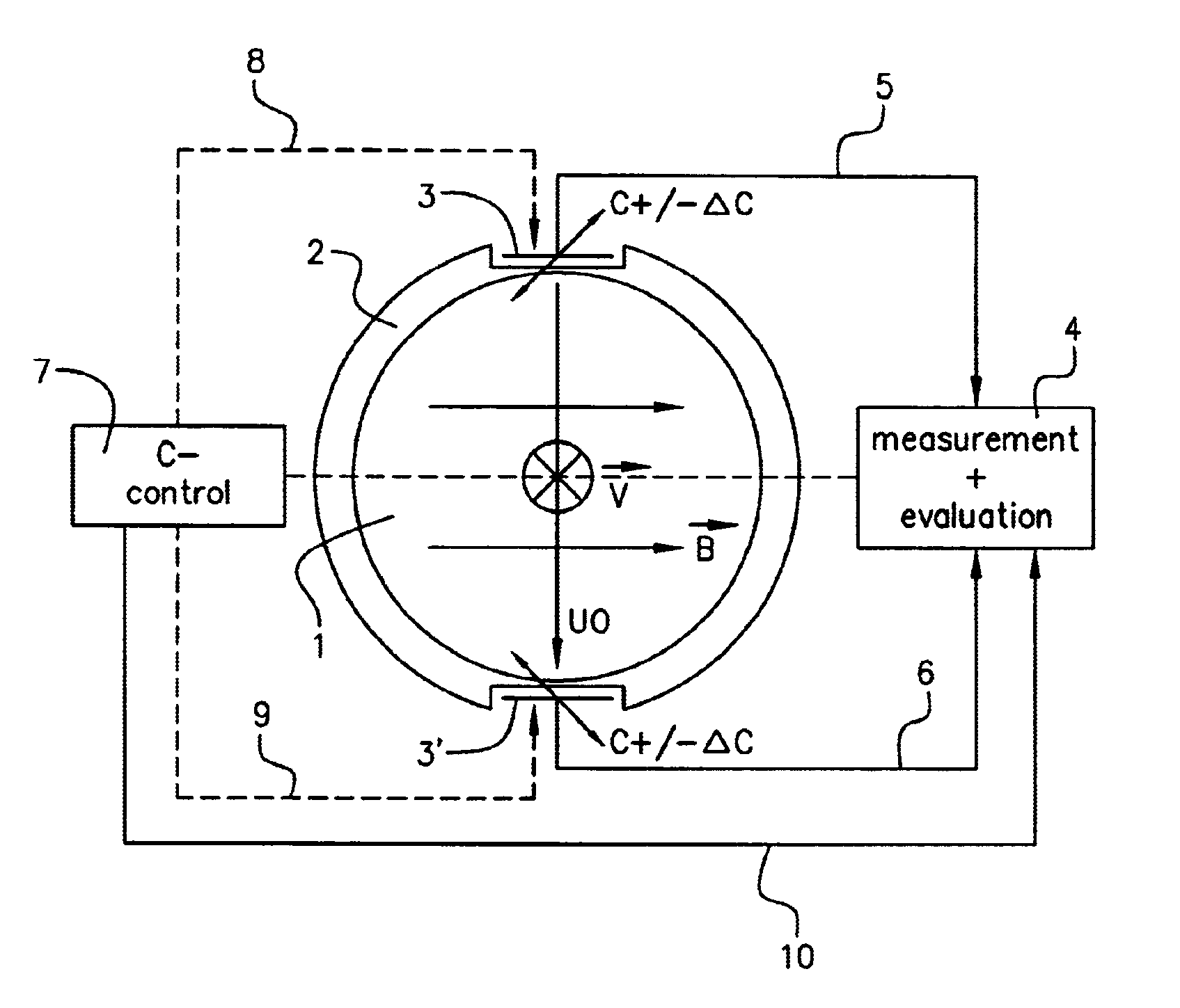
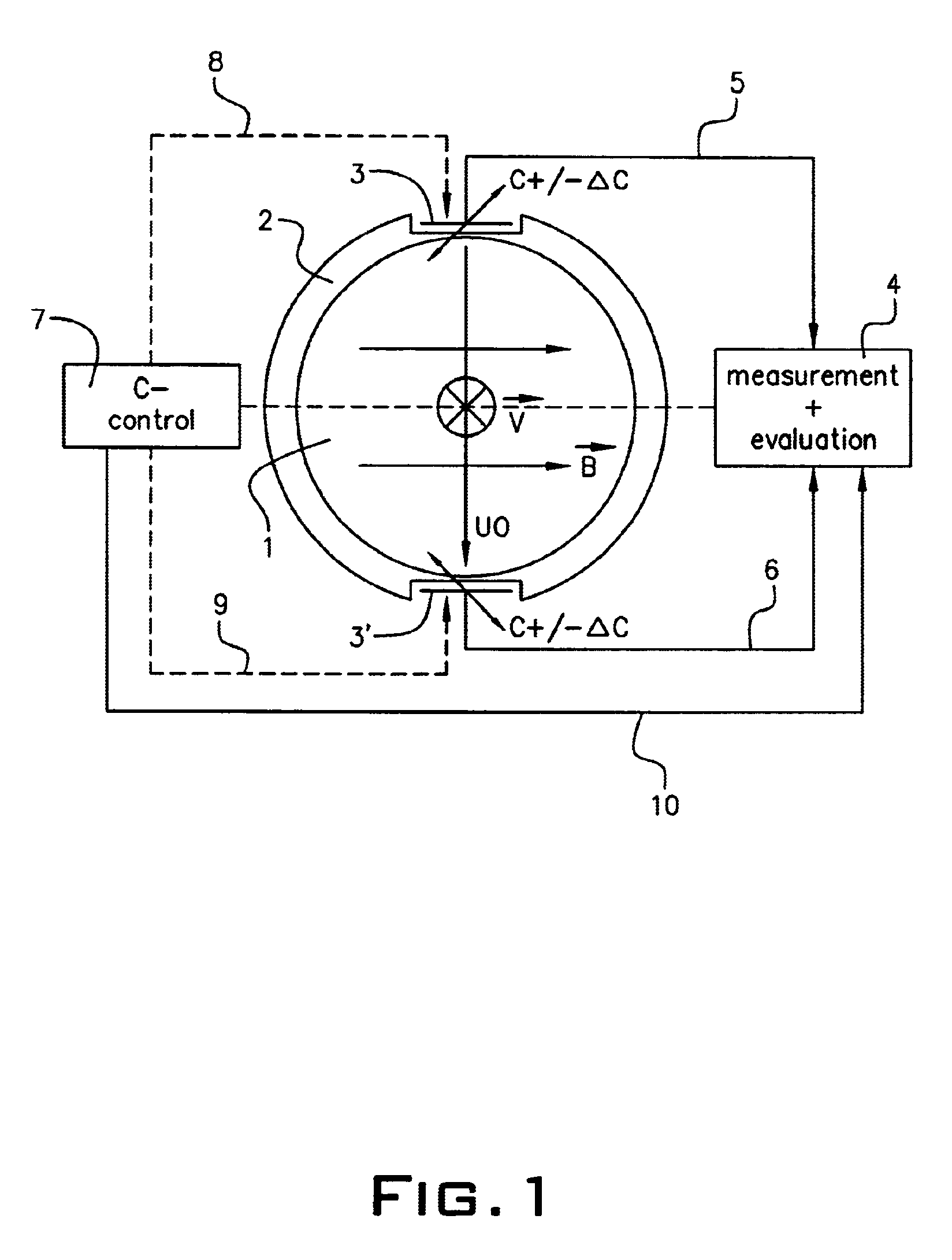
[0020]On an axis orthogonal to the magnetic field lines designated B in the drawing are provided coupling out electrodes 3, 3′ positioned outside the electrically insulating measuring tube 2, whereof the size of at least one can be modified by the control device 7 connected thereto (indicated by a sloping double arrow). Together with the tube interior the coupling out electrodes form capacitive units, which are used for coupling out the voltage UO induced in the interior 1 of the measuring tube 2 as a result of the interaction between the flow rate V and magnetic field B, in that the charge change occurring as a consequence of a capacitance change of the capacitive units is established in a measuring and evaluating device 4 connected by means of connections 5, 6, whereby from the same the useful voltage UO is determined and finally, using known laws, the flow rate is established therefrom.

[0021]The following explanations serve in exemplified manner only for deriving the relationship...


PUM


Abstract

A method for measuring a flow rate of a medium through a measuring tube which is penetrated by a constant magnetic field orthogonal to a flow direction and in which an electrical voltage building up in the medium is sensed by electrodes, insulted with respect to the medium and located on an outer wall of the measuring tube in a plane orthogonal to the flow direction of the medium, in which the capacitance of at least one capacitive unit is formed by the electrodes, and a measuring tube interior area and a charge change brought about by a change to the at least one capacitive is determined, and from this a voltage is established which is determinative of the flow rate of the medium through the measuring tube.

Description

PRIOR APPLICATIONS[0001]This application bases priority on International Application No. PCT / DE03 / 01375, filed Apr. 25, 2003, which in turn bases priority on German Application No. DE 102 21 677.0, filed May 16, 2002.BACKGROUND OF THE INVENTION[0002]1. Field of the Invention[0003]The invention relates to a method for measuring the flow rate of a medium flowing through a measuring tube and which is penetrated by a constant magnetic field positioned orthogonally to the flow direction, in which the electrical voltage building up in the medium is sensed by electrodes located in the plane of the magnetic field and externally on the electrically insulating wall of the measuring tube.[0004]2. Description of the Prior Art[0005]It is known to establish the flow of a medium through a measuring tube by capacitive measurement of the electrical voltage building up in the medium (Helmut Brockhaus, Magnetoinductive Flow Measurement with Capacitive Methods, in the Journal TM—Technisches Messen, 64,...

Claims


Application Information

Patent Timeline
IPC IPC(8): G01F1/58G01F1/60
CPCG01F1/60G01F1/584
Inventor STANGE, GERD
Owner ZYLUM BETEILIGUNGSGMBH & PATENTE II
Why Eureka
Try Eureka