Atomic oscillator and frequency signal generation system

a technology of atomic oscillators and frequency signals, applied in the field of atomic oscillators and frequency signal generation systems, can solve the problems of frequency fluctuations and lower frequency stability of atomic oscillators, and achieve the effect of improving reliability and reducing the light output of semiconductor lasers

Active Publication Date: 2020-06-09
MICROCHIP TECH INC
View PDF7 Cites 0 Cited by
  • Summary
  • Abstract
  • Description
  • Claims
  • Application Information

AI Technical Summary

Benefits of technology

[0006]An advantage of some aspects of the invention is to provide an atomic oscillator in which variations of light output of a semiconductor laser may be reduced. Another advantage of some aspects of the invention is to provide a system including the atomic oscillator.
[0009]In the atomic oscillator, the distance between the second temperature control element and the semiconductor laser is smaller than the distance between the first temperature control element and the semiconductor laser, accordingly, the temperature of the semiconductor laser is controlled using the second temperature control element, and thereby, the temperature of the semiconductor laser may be controlled faster than in the case where the temperature of the semiconductor laser is control led using the first temperature control element. Therefore, in the atomic oscillator, the control of the oscillation wavelength of the semiconductor laser may be performed by control of the second temperature control element based on the detection signal of the light receiving element.
[0022]The system includes the atomic oscillator in which the fluctuations of the light output of the semiconductor laser may be reduced, and may have better reliability.

Problems solved by technology

Variations of the light output of the semiconductor laser may cause frequency fluctuations (frequency fluctuations due to AC Stark effect) of the atomic oscillator and lower frequency stability of the atomic oscillator.

Method used


Image

  • Atomic oscillator and frequency signal generation system
  • Atomic oscillator and frequency signal generation system
  • Atomic oscillator and frequency signal generation system

Examples


Embodiment Construction

[0032]Embodiments of the invention will now be explained in detail with reference to the drawings. Note that the embodiments to be explained below do not limit the scope of the invention described in the Claims. Further, not all of the configurations to be explained are necessarily essential components of the invention.

1. Atomic Oscillator

1.1. Configuration of Atomic Oscillator

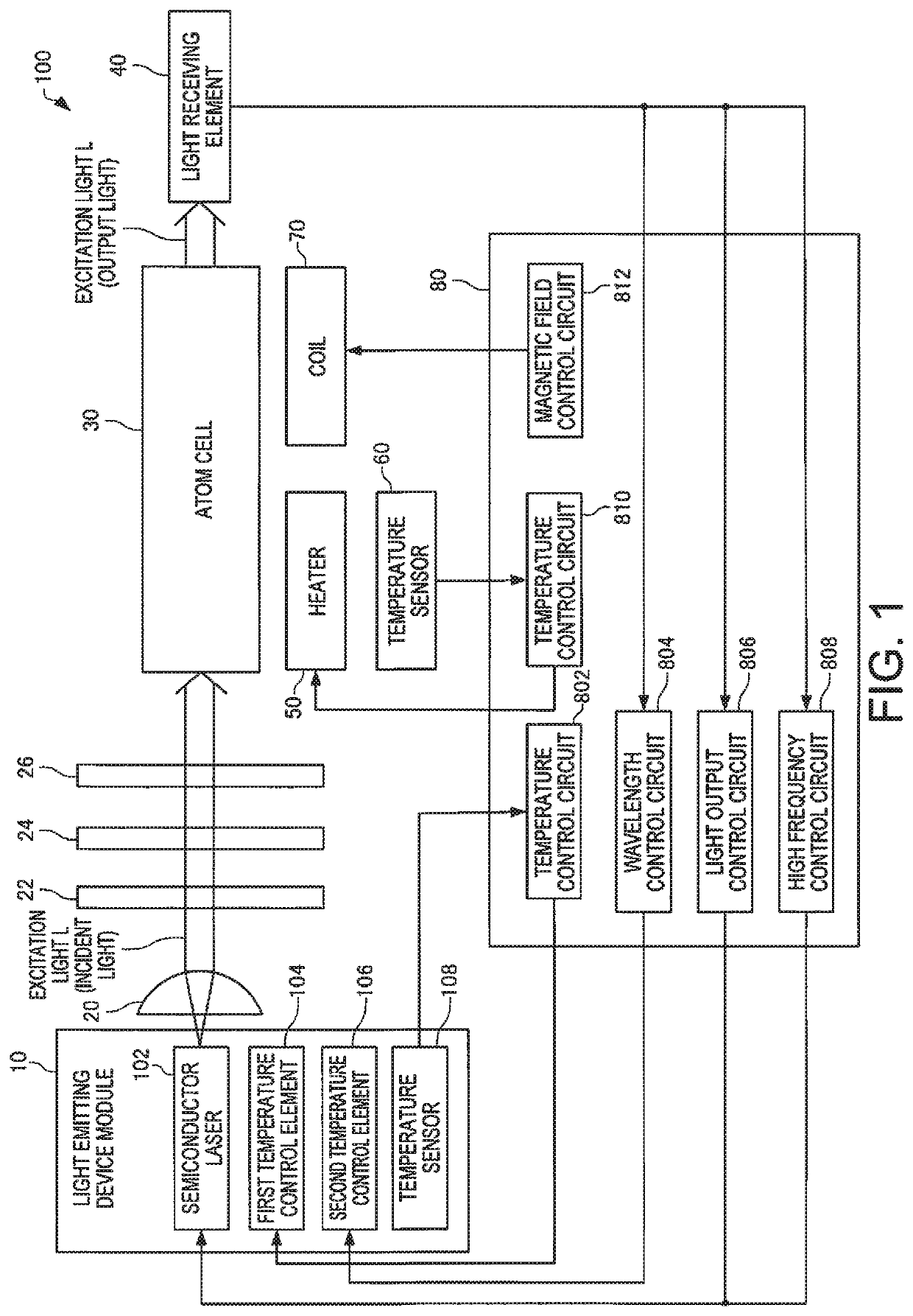
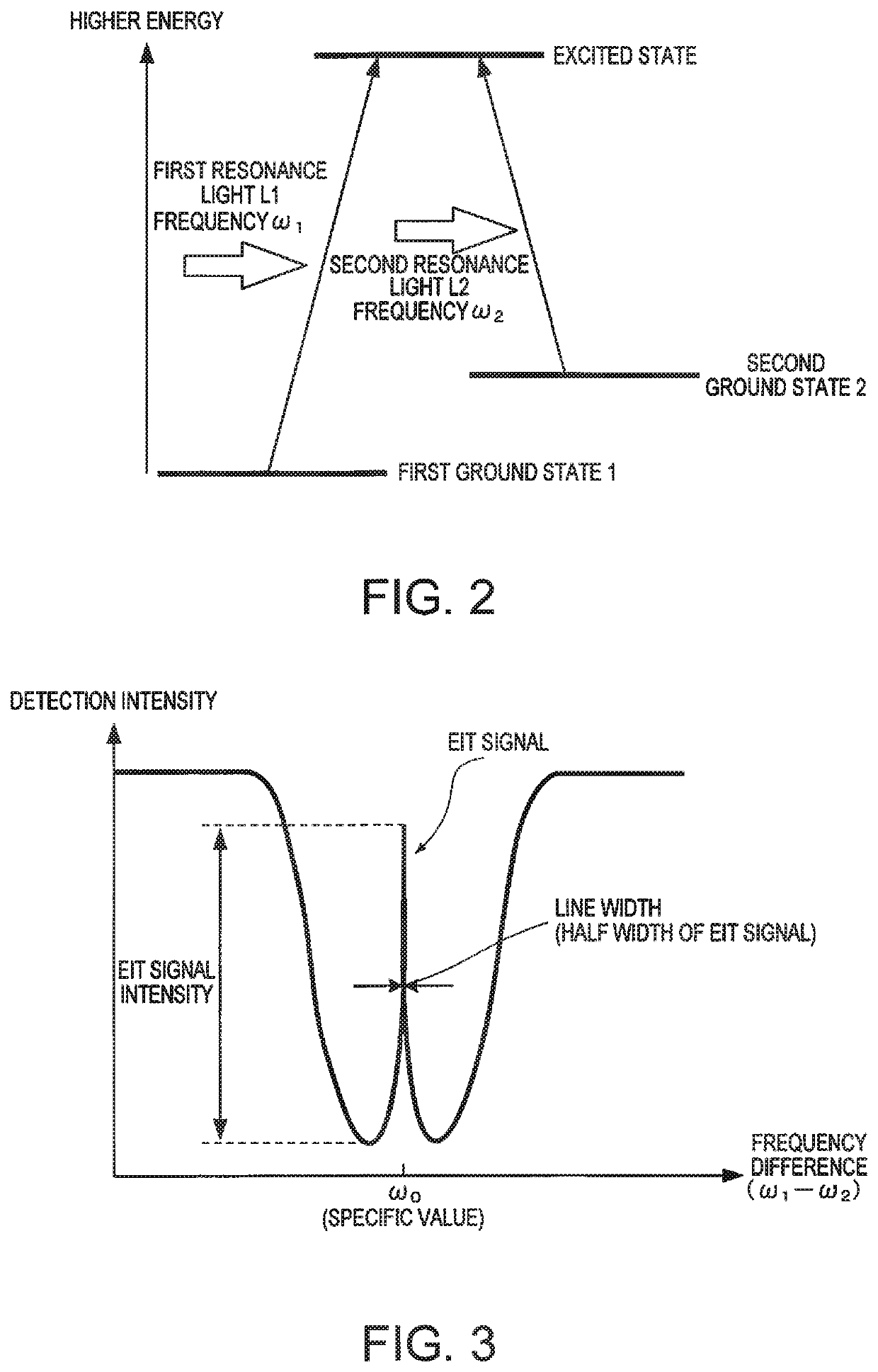
[0033]First, a configuration of an atomic oscillator according to an embodiment will be explained with reference to the drawings. FIG. 1 is a functional block diagram of an atomic oscillator 100 according to the embodiment. FIG. 2 is a diagram for explanation of energy states of an alkali metal atom within an atom cell 30 of the atomic oscillator 100 according to the embodiment. FIG. 3 is a graph showing a relationship between a frequency difference between two lights output from a semiconductor laser 102 and detection intensity detected in a light receiving element 40 in the atomic oscillator 100 according to...


PUM

PropertyMeasurementUnit
temperatureaaaaaaaaaa

Abstract

An atomic oscillator includes a semiconductor laser housed in a container, an atom cell housing alkali metal atoms and irradiated with a light output from the semiconductor laser, a light receiving element that detects an intensity of the light transmitted through the atom cell and outputs a detection signal, a temperature sensor housed in the container, a first temperature control element housed in the container and controlled based on output of the temperature sensor, and a second temperature control element housed in the container and controlled based on the detection signal. A distance between the second temperature control element and the semiconductor laser is smaller than a distance between the first temperature control element and the semiconductor laser.

Description

BACKGROUND1. Technical Field[0001]The present invention relates to an atomic oscillator and frequency signal generation system.2. Related Art[0002]Recently, atomic oscillators using CPT (Coherent Population Trapping) as a quantum interference effect have been proposed in the hopes of downsizing and lowering the power consumption of various apparatuses. The atomic oscillator using CPT is an oscillator using an electromagnetically induced transparency phenomenon (EIT phenomenon) that, when coherent lights having two different wavelengths (frequencies) are applied to alkali metal atoms, absorption of the coherent lights is stopped.[0003]As an atomic oscillator using the EIT phenomenon, for example, JP-A-2015-119152 discloses an atomic oscillator that controls the frequency (wavelength) of a resonance light output from a light emitting device module based on the detection result of a photodetector that detects light transmitted through an atom cell.[0004]In a semiconductor laser forming...

Claims


Application Information

Patent Timeline
Patent Type & Authority Patents(United States)
IPC IPC(8): H01S1/06H03L7/26H01S5/068H01S5/024G01K7/22H01S5/183G01K7/02H03B17/00H01S5/0687H03L1/04H01S5/022
CPCH03L1/04H01S5/0687H01S5/183H01S5/06804G01K7/22G01K7/02H03L7/26H03B17/00H01S5/02415H01S5/02216H01S5/02453H01S5/02248H01S5/02325G04F5/145
Inventor NISHIDA, TETSUO
Owner MICROCHIP TECH INC
Why Eureka
Try Eureka