
Fastening arrangement with tolerance compensation, and method for pre-assembly and assembly

a technology of tolerance compensation and fastening arrangement, which is applied in the direction of washers, screws, load-modified fasteners, etc., can solve the problems of affecting the stability, integrity and usability releasing the adjusting element from the basic element only with high effort or not at all, and achieving the effect of effective installation of the fastening arrangemen

Active Publication Date: 2017-09-26
BOLLHOFF VERBINDUNGSTECHNIK GMBH
View PDF27 Cites 7 Cited by
  • Summary
  • Abstract
  • Description
  • Claims
  • Application Information

AI Technical Summary

Benefits of technology

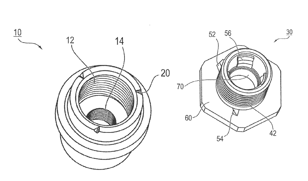
[0010]Further, the fastening arrangement according to the invention is provided with a first and a second anti-twist protection between the adjusting element and the basic element. The first anti-twist protection represents a transport safeguard or protection provided by a releasable locking connection between the basic element and the adjusting element. The second anti-twist protection safeguards the fastening arrangement against a locking of the basic element and the adjusting element, meaning that the second anti-twist protection prevents a screwing-in of the adjusting element into the basic element which is too tight. To this end, the second anti-twist protection blocks at a specific angle position between the adjusting element and the basic element a further screwing-in of the adjusting element into the basic element. By means of these combined first and second anti-twist protections, the safe and related transport of the fastening arrangement consisting of the basic element and the adjusting element is ensured as well as an efficient assembling of the fastening arrangement between the components A and B. The first and the second anti-twist protections are realized in different constructive ways. According to different preferred embodiments of the invention, which will be explained in detail below, they are realized in elements which are separated from each other or commonly in only one element.
[0013]The second anti-twist protection is formed preferably compact, stable and not springy due to its functionality. In this way, the second anti-twist protection constitutes a blocking which blocks the rotational movement of the adjusting element against a further screwing-in of the adjusting element into the basic element. For this purpose, preferably the radially protruding web of the second anti-twist protection engages a recess at the basic element adapted thereto which prevents an over-screwing of this blocking connection due to the non-springy construction of the second anti-twist protection and the adapted shape of the recess in the basic element. In this context, it is preferred that the radially protruding web of the second anti-twist protection or lock safeguard has an upsetting or compression surface oriented almost radial with respect to the adjusting element by means of which a surface of at least one recess at the basic element may be abutted. For defining the orientation of the mentioned compression surface, the surface normal arranged on the compression surface is viewed, which is aligned according to the invention preferably in tangential direction with respect to the adjusting element. Preferably, the compression surface of the second anti-twist protection or lock safeguard cooperates with a surface in the recess at the basic element which is arranged parallel or almost parallel thereto. The surfaces adapted in this manner in their orientation with respect to each other ensure that a torque applied to the adjusting element is directed into the basic element to prevent a further screwing-in of the adjusting element into the basic element. According to an embodiment of the present invention, the surface normal of the compression surface is arranged in an angle smaller 90° with respect to the longitudinal axis of the adjusting element and thus arranged inclined in the screw-in direction into the basic element. In this way, it is ensured that the compression surface is aligned almost parallel to the contact surface in the recess.
[0015]With respect to the construction of the fastening arrangement, the adjusting element consists preferably of a multi-part construction having a central dragging-safeguard-component. For providing a space-saving construction of the fastening arrangement, the central dragging-safeguard-component comprises at least one radially inwardly protruding dragging arm as well as the radially outwardly protruding first and second anti-twist protections. The central dragging-safeguard-component is constructed so that the at least one dragging arm is arranged radially inside and the anti-twist protection radially outside of the sleeve shaped adjusting element. By means of this central dragging-safeguard-component, preferably the production of the adjusting element is simplified and the number of individual parts of the adjusting element is reduced.
[0019]For ensuring an effective installation of the fastening arrangement between the components A and B, the fastening arrangement is first pre-assembled before distribution. This method for pre-assembly of the fastening arrangement comprises the following steps: screwing-in of the adjusting element into the basic element, locking of the first anti-twist protection of the adjusting element in a first recess at the basic element and blocking of the second anti-twist protection of the adjusting element in a second recess at the basic element so that a locking of the adjusting element and the basic element is prevented. In this way, and preferably according to the invention, the adjusting element is screwed sufficiently deep into the basic element so that an installation between the components A and B is prepared. At the same time, it is also prevented that the adjusting element has been locked with the basic element during the pre-assembly which would guarantee a lose-proof transport of the adjusting element in the basic element but would require additional time for releasing the connection between the adjusting element and the basic element during assembly of the fastening arrangement between the components A and B. As a consequence, the method for pre-assembly prepares an effective and time-saving installation of the fastening arrangement between the components A and B.

Problems solved by technology

Further, the usage of plastics for producing the fastening arrangement may come along with disadvantages concerning the stability, integrity and usability of the fastening arrangement in chemical aggressive media or in a thermally burdened surrounding.
In this manner, the transport safeguard can be made catchingly and is undoable.
At the pre-assembly of known fastening arrangements it has shown, however, that despite of the transport safeguard the adjusting element was fixable at the basic element so tightly that a releasing of the adjusting element from the basic element was only possible with high effort or not at all.
This complicates, however, the installation of the fastening arrangement between the two components and is time consuming, which has a negative influence on an effective installation procedure of the fastening arrangement.

Method used


Image

  • Fastening arrangement with tolerance compensation, and method for pre-assembly and assembly
  • Fastening arrangement with tolerance compensation, and method for pre-assembly and assembly
  • Fastening arrangement with tolerance compensation, and method for pre-assembly and assembly

Examples


Embodiment Construction

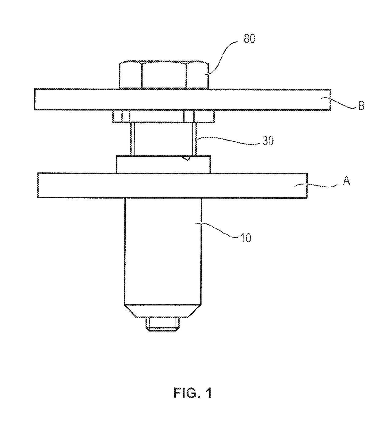
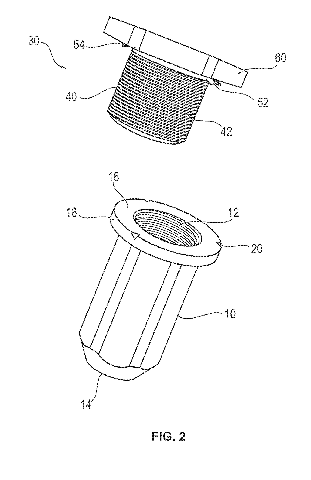
[0035]FIG. 1 shows a preferred embodiment of the fastening arrangement according to the invention for fastening a component B at a component A with automatic tolerance compensation between the components A and B. The fastening arrangement comprises therefore a basic element 10 which is fixed in an opening of the component A. An adjusting element 30 is connected to the basic element 10 via a screw connection. According to the rotational direction of the adjusting element 30, the common axial length of the basic element 10 and the adjusting element 30 varies, whereby tolerances between the two adjacent components A, B are compensable.

[0036]In the assembled state of the fastening arrangement, the adjusting element 30 supports itself at the second component B. The components A and B as well as the fastening arrangement 10, 30 are connected to each other via a mounting screw or fastening screw 80. Therefore, the fastening screw 80 is screwed into a threaded portion 14 in the basic elemen...


PUM

PropertyMeasurementUnit
angleaaaaaaaaaa
angleaaaaaaaaaa
angleaaaaaaaaaa

Abstract

The present invention relates to a fastening arrangement for fastening a component A to a component B with automatic tolerance compensation between the components A and B. The fastening arrangement comprises a fixable base element into which a mounting screw can be screwed via a first thread pair, and an adjusting element with an external thread that can be screwed into the base element via a second thread pair, wherein a first and a second anti-rotation safeguard are provided between the base element and the adjusting element, wherein said anti-rotation safeguards can be used to prevent detachment of the adjusting element from the base element during transport as well as locking of the adjusting element with the base element.

Description

1. FIELD OF THE INVENTION[0001]The present invention relates to a fastening arrangement for fastening a component B at a component A with automatic tolerance compensation between the components A and B. Further, the present application relates to a method for pre-assembly of this fastening arrangement as well as a method for assembly of this fastening arrangement.2. BACKGROUND OF THE INVENTION[0002]In the prior art, different constructions of fastening arrangements for fastening a component to another component with automatic tolerance compensation between these components are known. Such fastening arrangements consist principally of a basic element fixed at the first component. For this purpose, the basic element is for example screwed into the first component, jammed there and thus fixed detachable or non-detachable. With the basic element, an adjusting element may be screwed-in via a thread pairing. This adjusting element is screwed out of the basic element to compensate toleranc...

Claims


Application Information

Patent Timeline
Patent Type & Authority Patents(United States)
IPC IPC(8): F16B43/02F16B5/02F16B39/32F16B41/00F16B31/02
CPCF16B5/025F16B5/0233F16B5/0283F16B31/02F16B39/32F16B41/00F16B41/002Y10T29/49881
Inventor METTEN, ANDREASFIGGE, HANS-ULRICH
Owner BOLLHOFF VERBINDUNGSTECHNIK GMBH
Learn More