Tensioner lever

a technology of tensioner lever and tensioner plate, which is applied in the direction of belt/chain/gearring, mechanical equipment, etc., can solve the problems of damage to the torsion coil spring or the attachment surface, and the operation of the tensioner plate may not be smooth. , to achieve the effect of simple structure, smooth attachment and large height or width

Active Publication Date: 2017-09-26
TSUBAKIMOTO CHAIN CO
View PDF3 Cites 5 Cited by
  • Summary
  • Abstract
  • Description
  • Claims
  • Application Information

AI Technical Summary

Benefits of technology

[0009]The present invention solves these problems and an object of the invention is to provide a tensioner lever that can, with a simple structure, reliably prevent displacement or detachment of a torsion coil spring, prevent the torsion coil spring from interfering with an attachment surface, and allow smooth attachment of the tensioner lever to the attachment surface.
[0011]According to one aspect of the present invention, the torsion coil spring includes a helical part loosely fitted on the outer circumferential surface of the boss, a pressing arm extending from one end of the helical part and making contact with the lever body, and a support arm extending from the other end of the helical part and supported on the attachment surface, and the outer circumferential surface of the boss includes a restricting protrusion formed at a position closer to the attachment surface than the helical part. This restricting protrusion can restrict the movement of the helical part on the outer circumferential surface of the boss toward the attachment surface side. This way, any possible displacement or detachment of the torsion coil spring from the lever body in a state before the tensioner lever is attached to the attachment surface is reliably prevented, and also, the torsion coil spring is reliably prevented from interfering with the attachment surface in a state after the tensioner lever has been attached to the attachment surface, with a simple structure.
[0012]Since displacement or detachment of the torsion coil spring from the lever body can be prevented, the tensioner lever can be smoothly attached to the attachment surface.
[0013]According to another aspect of the present invention, the restricting protrusion is formed on the side of an imaginary line toward which the pressing arm presses the lever body, the imaginary line passing through a contact point between the pressing arm and the lever body and a center of the boss. By forming the restricting protrusion at a position where there is only a small gap or no gap between the helical part of the torsion coil spring and the outer circumferential surface of the boss both before and after attaching the tensioner lever to the attachment surface, the movement of the helical part toward the attachment surface side can be restricted reliably without designing the restricting protrusion to have a large height or width. Since the restricting protrusion can be designed to have a small height and width, the restricting protrusion can be prevented from becoming a hindrance to the operation of mounting the torsion coil spring to the lever body.
[0014]According to another aspect of the present invention, the restricting protrusion is formed to include a portion where a second imaginary line intersects with the outer circumferential surface of the boss, the second imaginary line being orthogonal to the imaginary line and passing through the center of the boss, whereby the movement of the helical part toward the attachment surface side can be restricted even more reliably without designing the restricting protrusion to have a large height or width.

Problems solved by technology

When attaching the tensioner lever to the attachment surface of an engine block or the like, an operator may sometimes have to perform the attachment operation without being able to see the torsion coil spring sufficiently.
The problem in such a case is that the torsion coil spring may be accidentally subjected to a force during the operation and may be displaced from or come off of the lever body, because of which sometimes the attachment operation of the tensioner lever may not be performed smoothly.
Even after the tensioner lever has been attached to the attachment surface of the engine block or the like, the helical part of the torsion coil spring may move on the outer circumferential surface of the boss toward the attachment surface side due to vibration or the like when the chain runs and the torsion coil spring may interfere with the attachment surface of the engine block or the like, which would lead to the problem of damage to the torsion coil spring or the attachment surface.

Method used


Image

  • Tensioner lever
  • Tensioner lever
  • Tensioner lever

Examples


Embodiment Construction

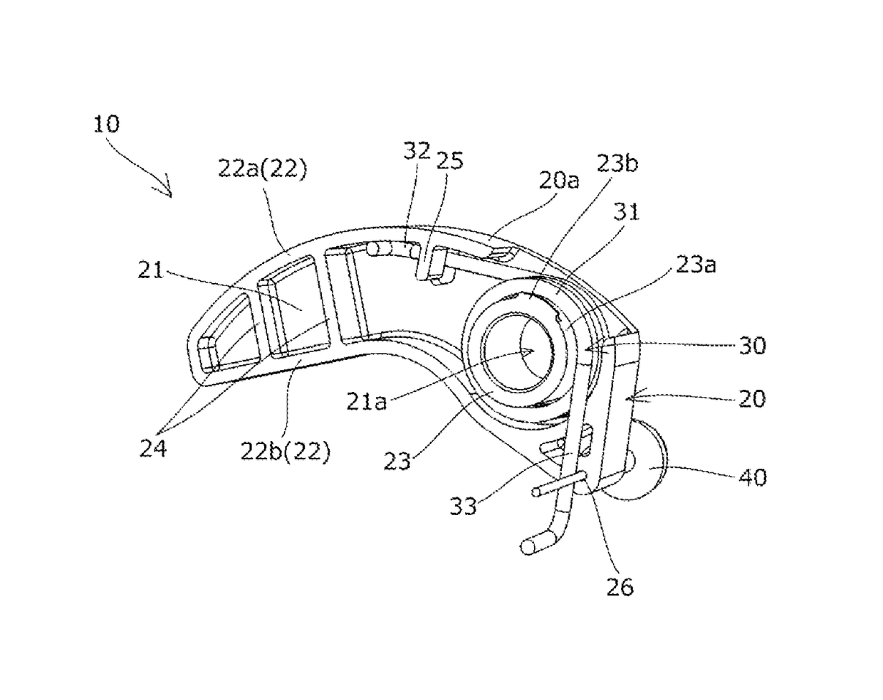
[0020]A tensioner lever 10 according to one embodiment of the present invention will be hereinafter described with reference to the drawings.

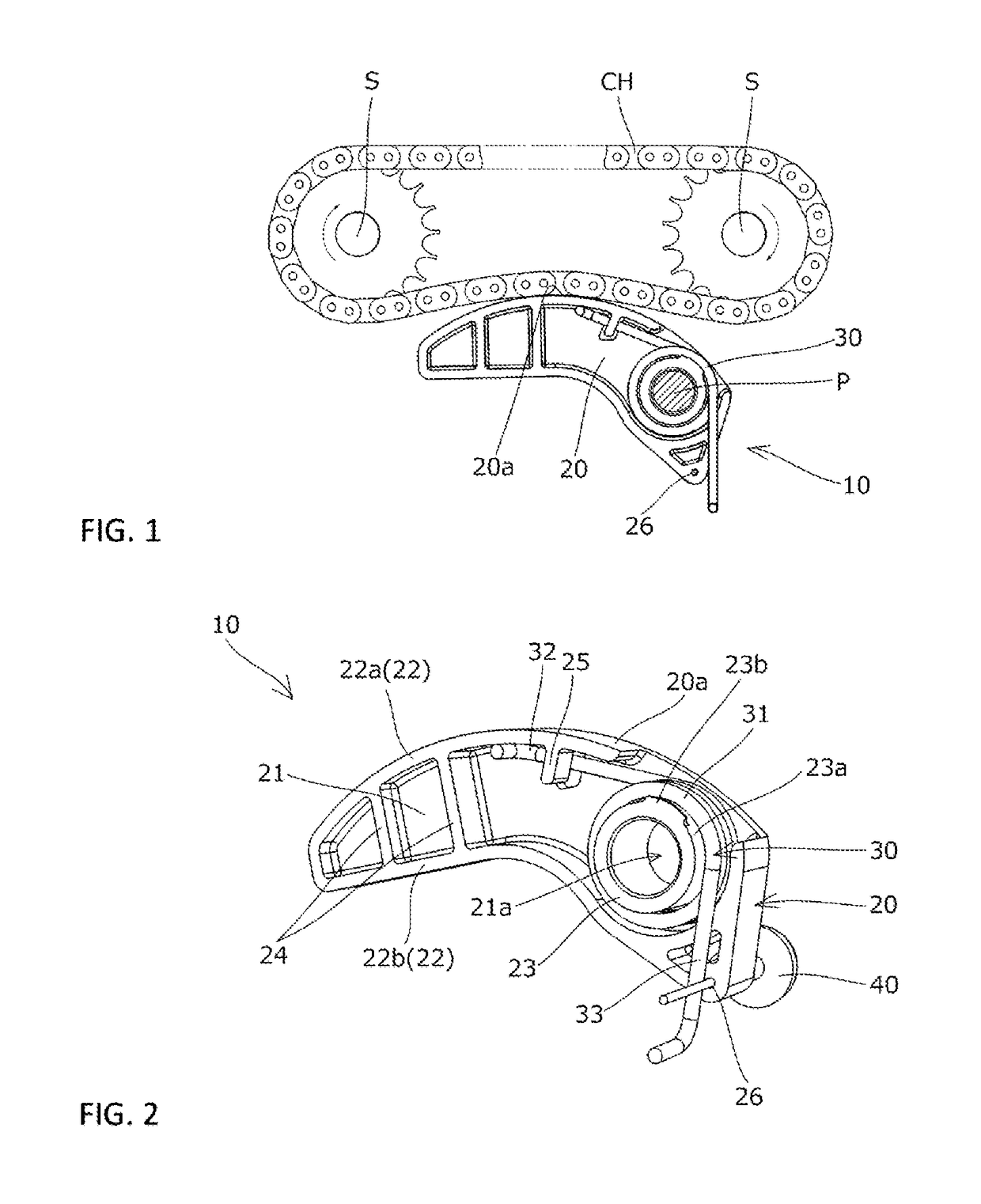
[0021]The tensioner lever 10, as shown in FIG. 1, is pivotably mounted on a pivot shaft P protruding from an attachment surface (not shown) of an engine block (not shown) or the like to slidably guide a chain CH running between a plurality of sprockets S to keep an appropriate chain tension.

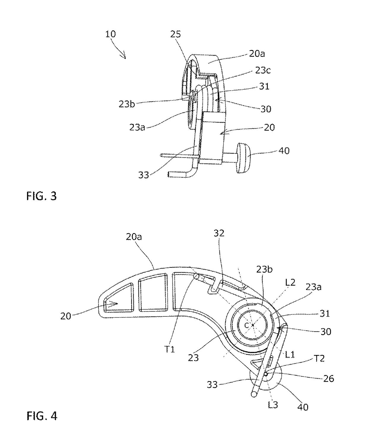
[0022]As shown in FIG. 2, the tensioner lever 10 includes a lever body 20 made of a synthetic resin or the like, a torsion coil spring 30 made of metal or the like, and a stopper pin 40.

[0023]The lever body 20 includes, as shown in FIG. 2 and FIG. 3, a planar base part 21 disposed a certain distance away from the attachment surface, a lever circumferential wall 22 standing upright from the peripheral edge of the base part 21 toward the attachment surface, a cylindrical boss 23 protruding from the peripheral edge of a shaft hole 21a formed in the base part 21...


PUM


Abstract

An object of the present invention is to provide a tensioner lever that can reliably prevent displacement or detachment of a torsion coil spring, prevent the torsion coil spring from interfering with an attachment surface, and allow smooth attachment of the tensioner lever to the attachment surface. The tensioner lever includes a lever body having a shoe surface, and a torsion coil spring pressing the shoe surface toward a chain. The lever body includes a base part and a cylindrical boss. The torsion coil spring includes a helical part loosely fitted on an outer circumferential surface of the boss, a pressing arm making contact with the lever body, and a support arm supported on the attachment surface. The outer circumferential surface of the boss includes a restricting protrusion formed at a position closer to the attachment surface than the helical part.

Description

BACKGROUND OF THE INVENTION[0001]1. Field of the Invention[0002]The present invention relates to a tensioner lever that slidably guides a running chain, and more particularly to a chain tensioner lever that slidably guides a chain by pressing a shoe surface of a lever body against the chain by the resilient force of a torsion coil spring.[0003]2. Description of the Related Art[0004]As an example of tensioner levers used to remove slackness in chains and to prevent vibration of running chains in conventional chain transmission devices used for driving auxiliary machines or the like of car engines, a tensioner lever, which is pivotably attached to an attachment surface of an engine block or the like and includes a lever body having a shoe surface that slidably guides the chain, and a torsion coil spring interposed between the lever body and the attachment surface to press the shoe surface toward the chain, has been known (see, for example, Japanese Patent Application Laid-open No. 201...

Claims


Application Information

Patent Timeline
Patent Type & Authority Patents(United States)
IPC IPC(8): F16H7/08
CPCF16H7/08F16H2007/081F16H2007/0872F16H2007/0893
Inventor NORO, KAZUSHI
Owner TSUBAKIMOTO CHAIN CO
Why Eureka
Try Eureka