Multi-beam antenna system and method for controlling output power thereof

a multi-beam antenna and output power technology, applied in the direction of antennas, power management, electrical equipment, etc., can solve the problems of low power usage efficiency, difficult to recompose the beam in accordance with a change of situation, and inconvenient long distance communication performance, etc., to achieve the effect of boosting the beam, less costly system development and easy realization

Inactive Publication Date: 2017-09-26
ELECTRONICS & TELECOMM RES INST
View PDF7 Cites 2 Cited by
  • Summary
  • Abstract
  • Description
  • Claims
  • Application Information

AI Technical Summary

Benefits of technology

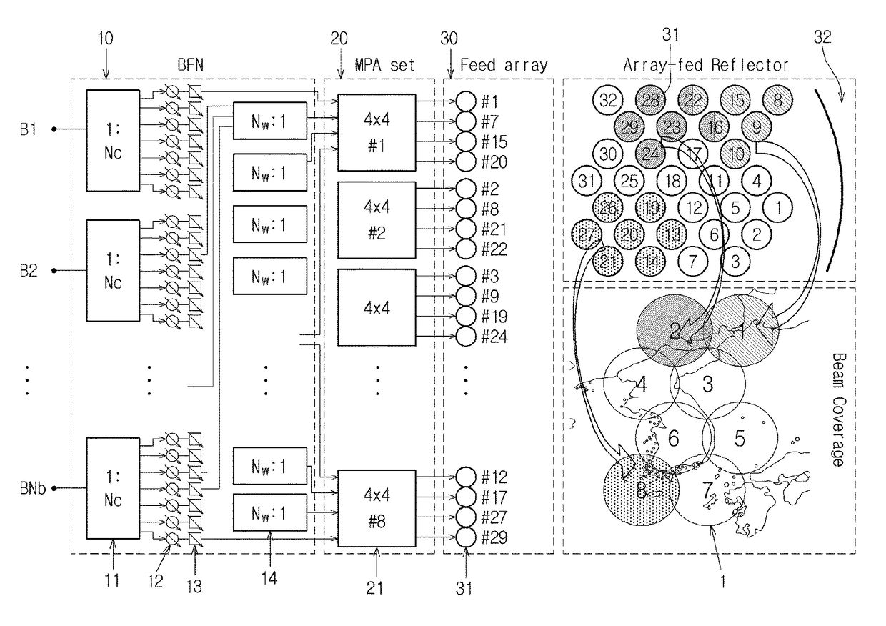
[0014]The present invention provides a multi-beam antenna system composing a beam by optimizing an antenna gain with amplitude & phase optimization (A&P), being able to reduce the number of variable phase shifters and variable attenuators by adjusting an output power of each beam without recomposing a beam form by phase optimization technique, utilizing resources efficiently, and optimizing performances.
[0033]Accordingly, the multi-beam antenna system and the method for controlling output power thereof according to the present invention can boost a beam in a certain service coverage by increasing an output power level without reconfiguring the form of beam. That is, since the numbers of variable phase converters and variable attenuators can be reduced as the form reconfiguration of beam is not needed, it becomes easier to realize and less costly to develop the system due to the simplified system. In addition, by setting the number of MPA to be equal to or greater than the number of feeds involved in forming a single beam, the frequency directivity of the MPA output port can be achieved, and by limiting the power of MPA within a margin of error to combine with feeds, antenna performance optimization as well as effective usage of resources can be achieved at the same time. Therefore, even with a high power amplifier having a relatively-low output, it is possible to form a boost beam without a decrease in performance and resource wastes.

Problems solved by technology

Although multi-beams can be realized easily as an SFPB (Single Feed per Beam) system, in which each of feeds forms an individual single beam, its performances are not suitable enough for long distance communication due to a low gain.
While a system having a multi-beam service coverage by having a plurality of feeds overlapped with one another can improve the directivity and gain of the beam greatly, it is difficult to recompose the beam in accordance with a change of situations.
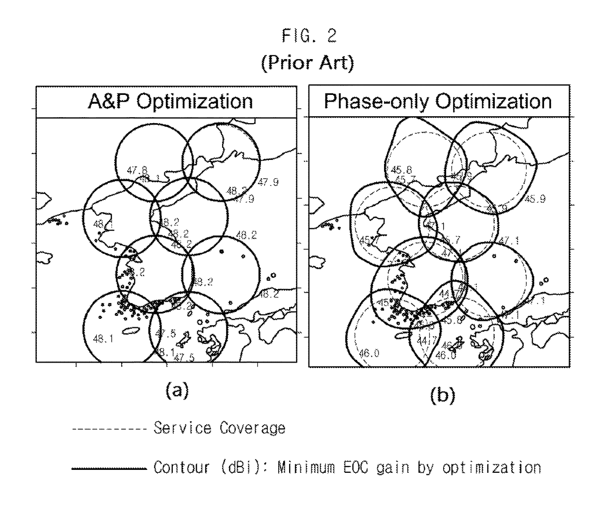
On the contrary, amplitude & phase optimization (A&P) takes advantage of optimizing of the antenna gain, but because of low power usage efficiency and high DC power consumption, the phase optimization (PO) is largely used to optimize an array antenna.
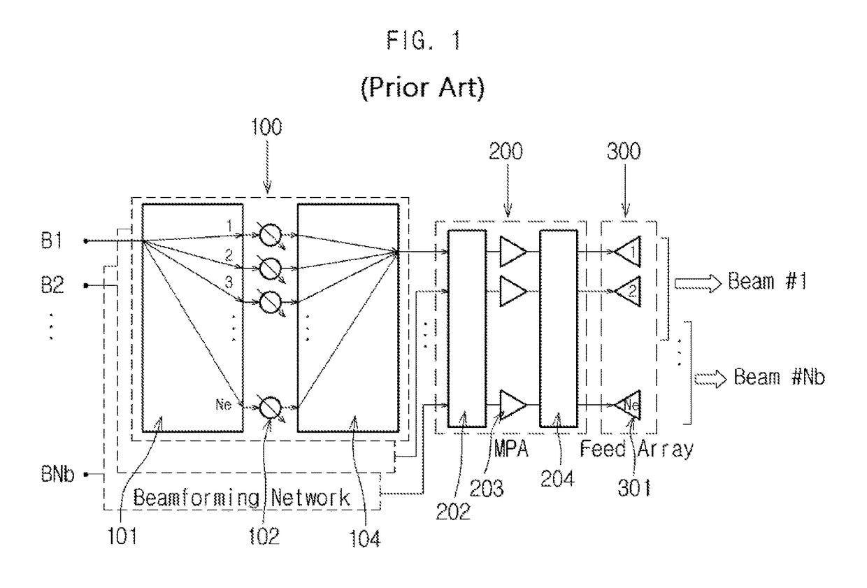
However, the phase array antenna system of FIG. 1 has a limitation in optimizing the antenna gain because it uses only the variable phase shifting portion 102 without the variable attenuator.
Moreover, it is difficult to realize and costly to produce the phase array antenna system of FIG. 1 because the phase array antenna system of FIG. 1 needs to have as many BFNs 100 as the number of beams (number of signals), a plurality of the variable phase shifting portions 102 are required despite much freedom in forming a beam as each BFN 100 divides and combines as many input signals as the number of feeds, and the number of ports for the divider 101 and combiner 104 are increased.
However, as described above, the phase optimization (PO) is largely used even though the EOC gain is degraded by the problems of power usage efficiency and DC power consumption.

Method used


Image

  • Multi-beam antenna system and method for controlling output power thereof
  • Multi-beam antenna system and method for controlling output power thereof
  • Multi-beam antenna system and method for controlling output power thereof

Examples


Embodiment Construction

[0045]The appended drawings and the descriptions on the drawings illustrating an embodiment of the present invention shall be referred to in order to understand the present invention, operational advantages of the present invention, and objects obtained by embodying the present invention.

[0046]Hereinafter, certain embodiments of the present invention will be described in detail with reference to the appended drawings. However, the present invention can be realized in various forms and shall not be limited to the described embodiments. For a clear description of the present invention, any portions irrelevant to the description will be omitted, and it shall be appreciated that same reference symbols in the drawings represent same elements.

[0047]When it is described that a certain portion “includes” a certain component, it does not mean to exclude other components but means to include other components unless otherwise described. In addition, the terms “portion”, “device”, “module”, “bl...


PUM


Abstract

Disclosed are a multi-beam antenna system and a method of controlling an output power thereof. An embodiment of the present invention includes a beam forming network configured to receive a plurality of signals to be a plurality of beams, to divide each of the plurality of signals to a plurality of divided signals, and to output a plurality of excited signals by adjusting and combining amplitude and phase of each of the plurality of divided signals, an MPA set having a plurality of MPAs configured to receive corresponding excited signals among the plurality of excited signals from the beam forming network and to control output powers of the received excited signals according to communication traffic, and a feed array having a plurality of feeds configured to form a multi-beam by being excited according to the amplitude and phase of the excited signals from the MPA set.

Description

BACKGROUND[0001]1. Technical Field[0002]The present invention relates to a multi-beam antenna system and a method for controlling an output power thereof, especially to a multi-beam antenna system and a method for controlling an output power thereof that can control a strength of a beam by controlling an output power without recomposing a form of the beam.[0003]2. Background Art[0004]A beam-forming technology is currently used by many kinds of communication systems to avoid wasting of resources, and the beam-forming technology is realized by utilizing a multi-beam antenna system. Although multi-beams can be realized easily as an SFPB (Single Feed per Beam) system, in which each of feeds forms an individual single beam, its performances are not suitable enough for long distance communication due to a low gain. While a system having a multi-beam service coverage by having a plurality of feeds overlapped with one another can improve the directivity and gain of the beam greatly, it is d...

Claims


Application Information

Patent Timeline
Patent Type & Authority Patents(United States)
IPC IPC(8): H04B7/185H01Q3/36H01Q25/00H04B7/0426H03F3/68
CPCH04B7/18515H01Q3/36H01Q25/007H03F3/68H04B7/0426H01Q21/00H04B7/0617H04W52/04
Inventor YUN, SO-HYEUNUHM, MAN-SEOKLEE, HONG-YEOLKWAK, CHANG-SOOYOM, IN-BOK
Owner ELECTRONICS & TELECOMM RES INST
Why Eureka
Try Eureka