Top-filling humidifier

a top-filling, humidifier technology, applied in air humidification systems, lighting and heating apparatuses, heating types, etc., can solve the problems of water spillage from the tank, water falling on the floor, and the user cannot wash the tank, so as to prevent accidental tipping and water spillage from contacting electrical and mechanical parts

Active Publication Date: 2017-10-03
GUANGDONG TITAN SMART ELECTRICAL APPLIANCE CO LTD
View PDF5 Cites 16 Cited by
  • Summary
  • Abstract
  • Description
  • Claims
  • Application Information

AI Technical Summary

Benefits of technology

[0032]In one example, the fan is disposed in an intermediate chamber having an air vent that is a height within a range of 5 to 10 mm above the mist chamber, th...

Problems solved by technology

Furthermore, other disadvantages of bottom-fill humidifier include that user cannot wash the tank.
In addition, there is an inherent difficulty in filling water.
Tank may fall on the floor and crack.
Furthermore, disadvantages of traditional air-supply channel are found when the fan directly supplies air into the mist-creating chamber.
Water would then short out the fan, and may even short out the electronics in the base.
In addition, because the fan is directly connected to the mist-creating chamber, when a user tilts the humidifier at a steep angl...

Method used


Image

  • Top-filling humidifier
  • Top-filling humidifier
  • Top-filling humidifier

Examples


Embodiment Construction

[0100]The embodiment and its various embodiments can now be better understood by turning to the following detailed description of the embodiments, which are presented as illustrated examples of the embodiment defined in the claims. It is expressly understood that the embodiment as defined by the claims may be broader than the illustrated embodiments described below.

[0101]Many alterations and modifications may be made by those having ordinary skill in the art without departing from the spirit and scope of the embodiment. Therefore, it must be understood that the illustrated embodiment has been set forth only for the purposes of example and that it should not be taken as limiting the embodiment as defined by the following claims. For example, notwithstanding the fact that the elements of a claim are set forth below in a certain combination, it must be expressly understood that the embodiment includes other combinations of fewer, more or different elements, which are disclosed herein e...


PUM

PropertyMeasurementUnit
Lengthaaaaaaaaaa
Lengthaaaaaaaaaa
Thicknessaaaaaaaaaa

Abstract

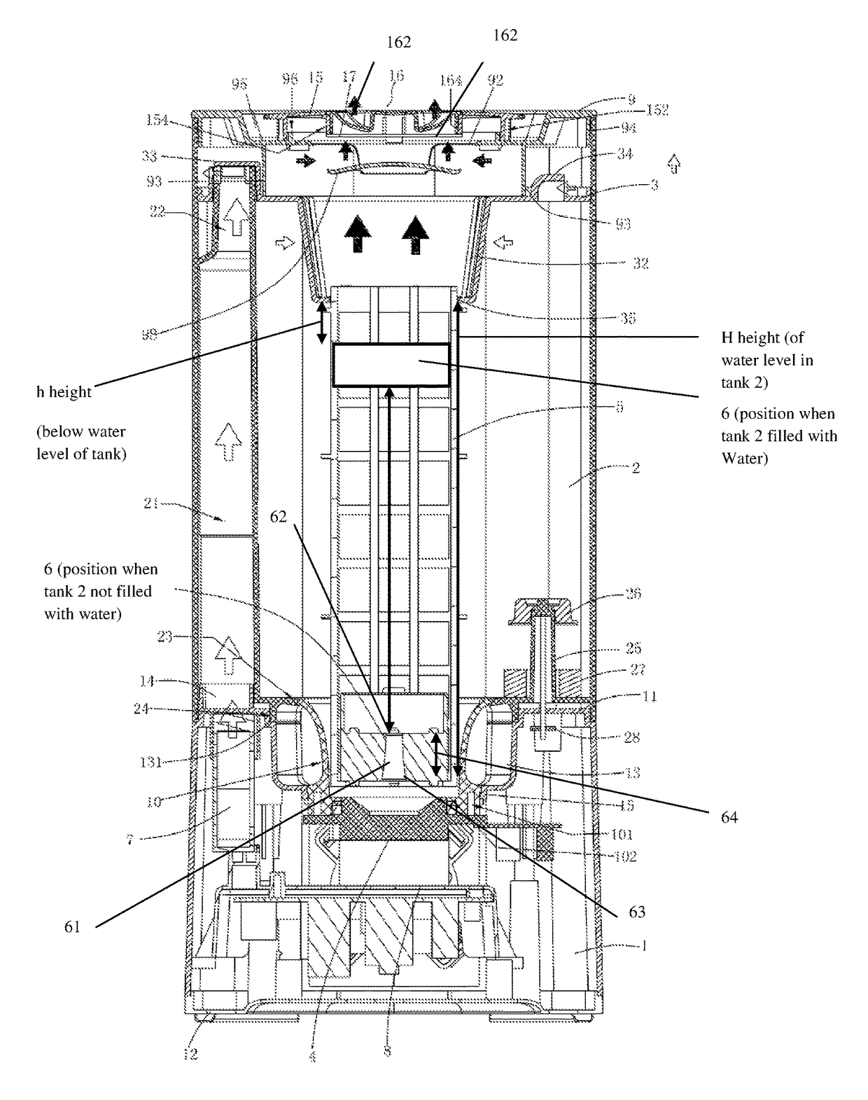
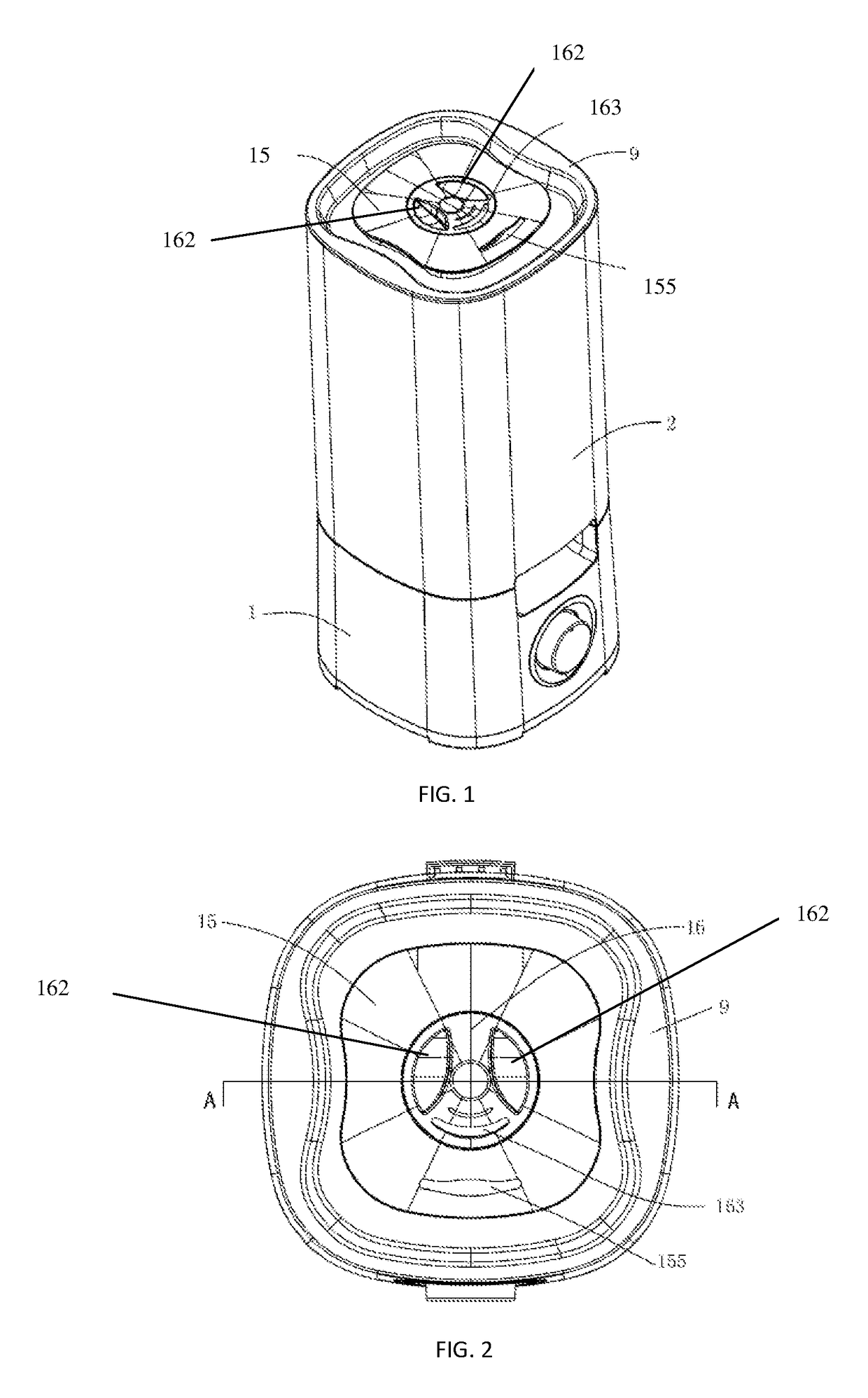
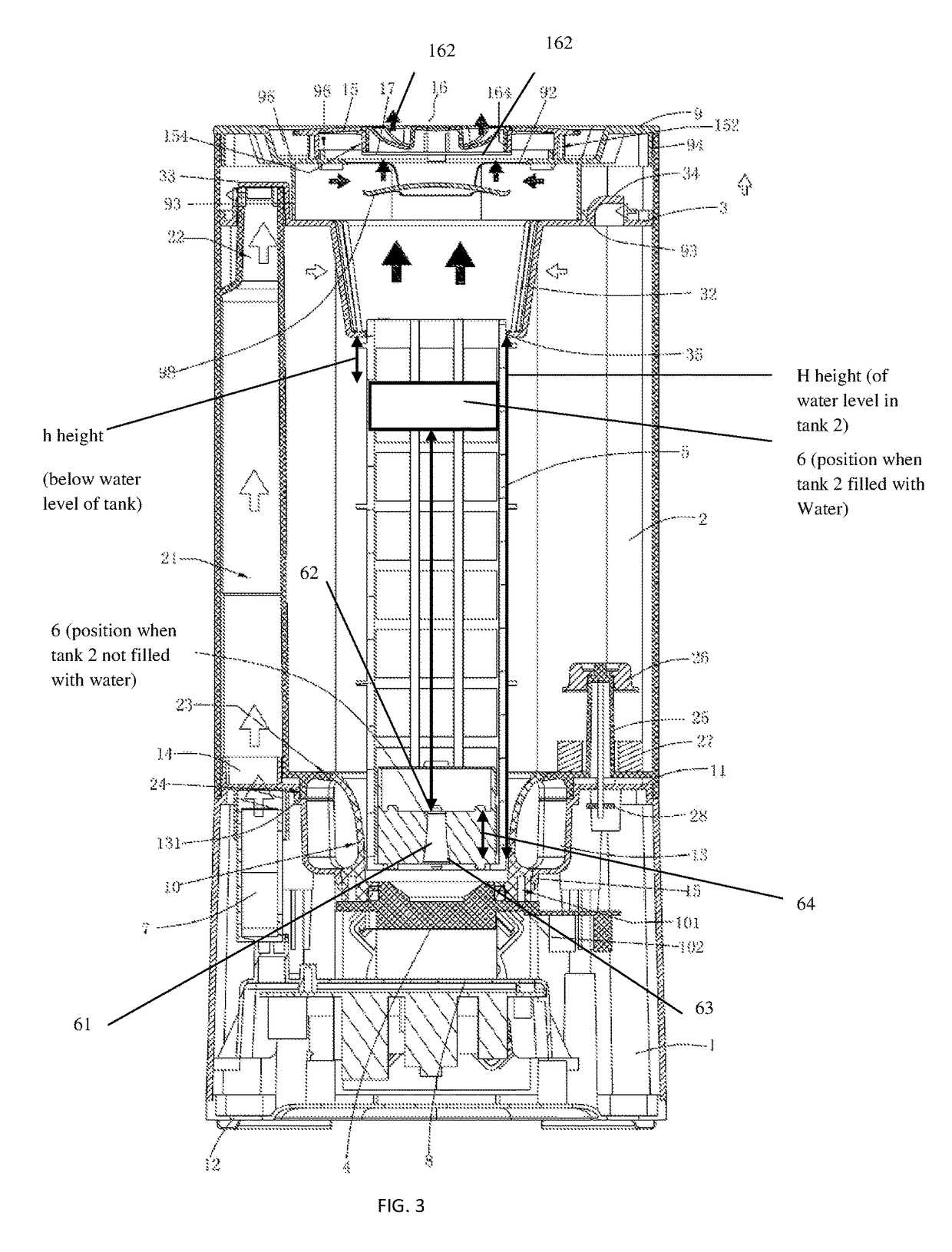
An ultrasonic humidifier includes a tank having a water level and a floater having a tubular structure with a bottom rim and a top rim. The tubular structure has a frusto-conical shape and is vertically and co-axially disposed within the floater. The tubular structure having a widest diameter end disposed on the bottom rim and a narrower diameter end disposed at the top rim. This humidifier also has an air-supply arrangement that eliminates water damage to the fan during spillage.

Description

FIELD OF THE DISCLOSURE[0001]The field of the disclosure is water misting devices in general and humidifier specifically.BACKGROUND OF THE DISCLOSURE[0002]There is a need for an improved misting device that provides a finer misting for users to enjoy.[0003]Despite numerous desirable properties in known humidifiers, these known humidifiers have several disadvantages. For example, known humidifiers or aromatic atomizers are designed to have a sealed tank having a screw cap located at the bottom of the tank. To add water, the user must remove the tank from the humidifier, invert it over, unscrew the cap, and then add water into the tank; and then after water is filled, screw the cap back on, invert it back and place the tank back on the humidifier. This is known as bottom-fill humidifier design. Conventional humidifiers use electronic ceramic vaporizer to produce high frequency (1.7 MHz) vibration to vaporize water.[0004]Furthermore, other disadvantages of bottom-fill humidifier includ...

Claims


Application Information

Patent Timeline
IPC IPC(8): B01F3/04F24F3/14
CPCF24F6/12B01F3/04F24F11/0008F24F13/20F24F6/00F24F2006/008F24F2006/143B01F23/20
Inventor LU, SHAO QUANYANG, YUZUO, LEI PENGWU, XIAN ANZUO, PENG FEIYAN, HAI FENGWANG, MU MIANHU, ZE HUI
Owner GUANGDONG TITAN SMART ELECTRICAL APPLIANCE CO LTD
Why Eureka
Try Eureka