
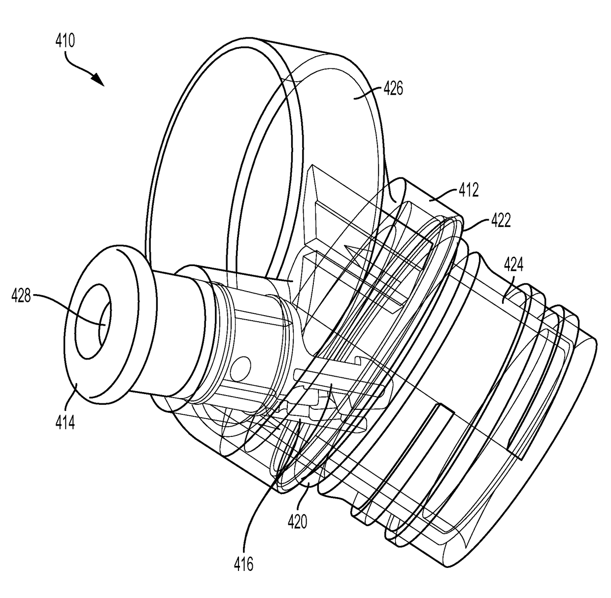
Bottle cap

a bottle cap and lid technology, applied in the field of sports caps, can solve the problems of progressively more difficult to drink from the bottle, the volume of air in the bottle can be changed, and the use of a conventional bottle cap with a nozzle is problematic, so as to facilitate the formation of an enclosed volum

Active Publication Date: 2017-10-03
HELEN OF TROY LIMITED
View PDF21 Cites 37 Cited by
  • Summary
  • Abstract
  • Description
  • Claims
  • Application Information

AI Technical Summary

Benefits of technology

The present patent is related to a sports cap for use with a rigid bottle or flask. The sports cap allows for easy consumption of liquid from the container without the need to remove the cap or lid. The sports cap is insulated to maintain the temperature of the liquid and provide access. It also helps to create an enclosed volume within the assembly body of a liquid dispensing accessory for rigid-walled liquid containers. The cap has a body with an annular wall and an aperture for a nozzle. The nozzle can be retracted or extended to control the flow of liquid. The nozzle has a longitudinal recess that allows air to flow through it and into the container when the nozzle is extended, and prevents air from flowing through it when the nozzle is retracted. This invention improves the user experience when consuming liquid from rigid containers.

Problems solved by technology

In addition, users may want to consume liquid from the container without removing the lid from the container, requiring a lid or cap that provides access to the liquids.
However, insulated bottles and flasks are sometimes rigid-walled and incompressible, which can make the use of a conventional cap with a nozzle problematic, because it is not possible to change the volume of air within the bottle.
Therefore, with a typical nozzle design that does not allow air to flow into the bottle as fluid flows out, a partial vacuum is created within the rigid-walled bottle as liquid is removed through the nozzle, making it progressively more difficult to drink from the bottle until the user stops drinking and allows air to flow back into the bottle through the nozzle.

Method used


Image

  • Bottle cap
  • Bottle cap
  • Bottle cap

Examples


Embodiment Construction

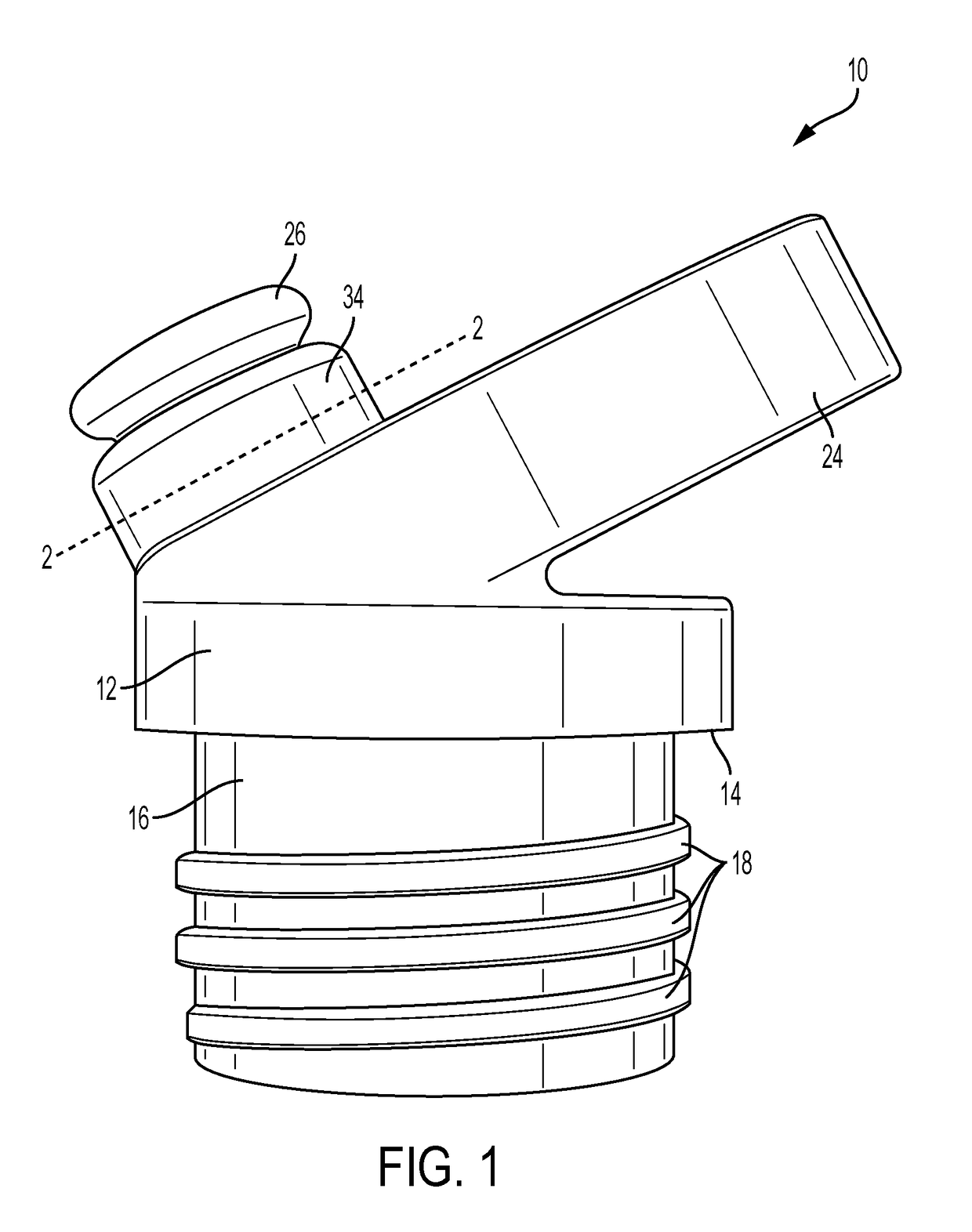
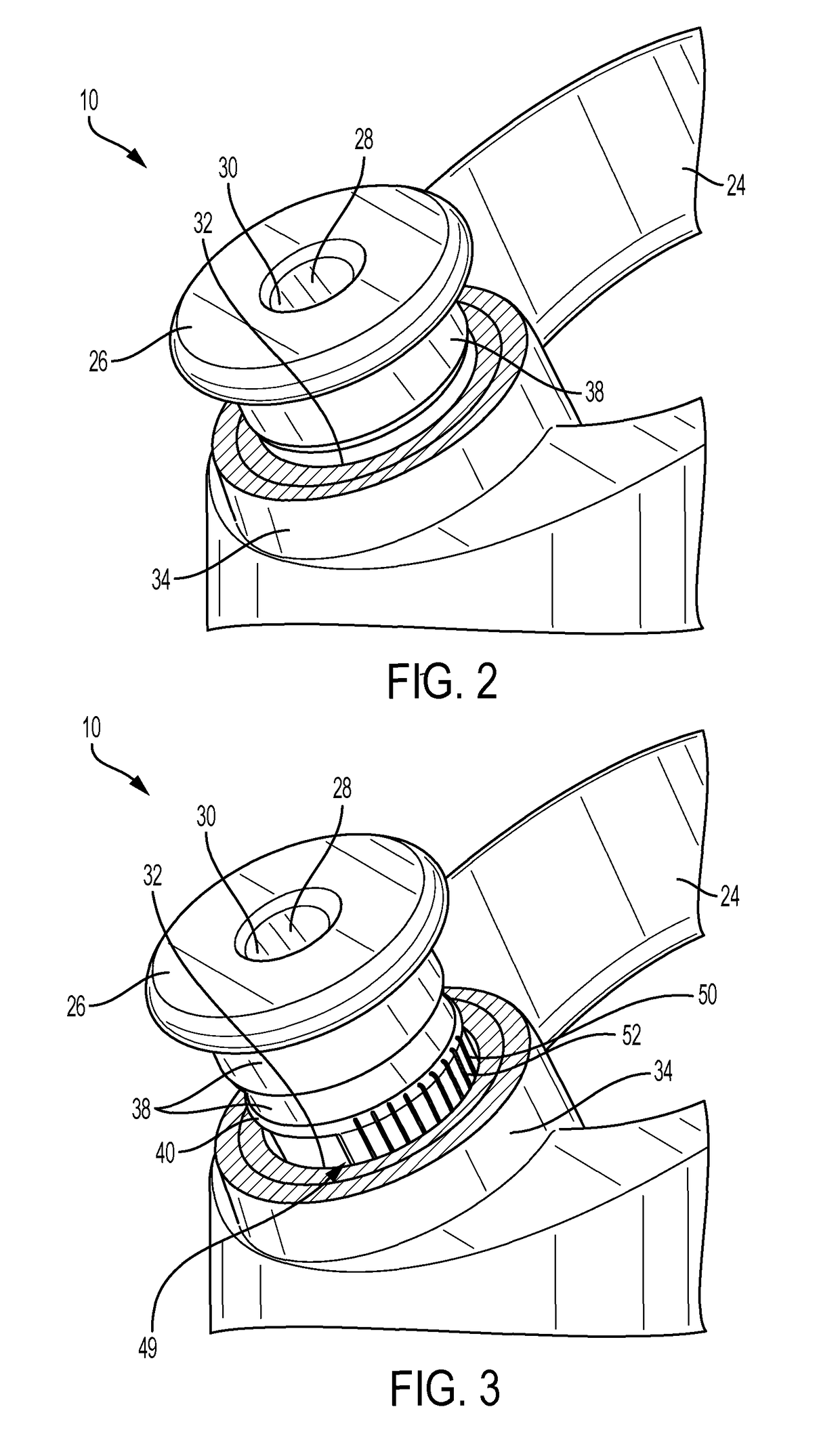
[0029]FIGS. 1-5 depict a first embodiment of a bottle or flask cap, generally indicated at 10, according to aspects of the present disclosure. Cap 10 includes a body 12, a nozzle 26, and a venting system 49. FIGS. 1-5 portray a generally cylindrical cap, but other shapes or dimensions may be appropriate depending on the size and shape of a bottle for use with the cap. Cap 10 may be made of one or more suitable materials, including plastic, aluminum, or steel, among others.

[0030]FIG. 1 is a perspective view of cap 10 showing body 12 and nozzle 26 in a retracted (closed) position. FIGS. 2-3 are enlarged views of an upper portion of cap 10 with material removed above the line 2-2 in FIG. 1, where the nozzle is in a retracted position in FIG. 2 and an extended position in FIG. 3. FIGS. 4-5 are sectional views of cap 10 taken along a central vertical plane with respect to FIG. 1, where the nozzle is in a retracted position in FIG. 4 and an extended position in FIG. 5. As seen in the sect...


PUM


Abstract

An embodiment of a cap for a bottle may comprise a body and nozzle. The body may include an annular wall, an aperture configured to receive a nozzle, and a plug rigidly attached within the aperture. The nozzle may be movable between a retracted position in which fluid cannot pass between plug and nozzle, and an extended position in which fluid can pass between plug and nozzle. The nozzle may include an inner wall and an outer wall. The outer wall may have at least one longitudinal recess. The longitudinal recess may allow selective passage of air. The longitudinal recess may allow air to flow through the recess and into the bottle when the nozzle is in the extended position, and is contained within the aperture and is thus configured to prevent air from flowing through the recess and into the bottle when the nozzle is in the retracted position.

Description

CROSS-REFERENCE TO RELATED APPLICATIONS[0001]This application claims priority from U.S. Provisional Patent Application Ser. Nos. 62 / 001,024, filed May 20, 2014, and 62 / 033,631, filed Aug. 5, 2014, each of which is hereby incorporated by reference.FIELD OF THE DISCLOSURE[0002]The present disclosure relates to lids or caps for drinking containers. More particularly, the present disclosure relates to a sports cap for use with relatively rigid, vacuum insulated flasks.BACKGROUND OF THE DISCLOSURE[0003]As people lead increasingly active lives, they may require an increased intake of liquids, which users may prefer to consume on the go and / or at a particular temperature. Containers such as sports bottles or insulated flasks may provide the user the convenience of readily available liquids maintained at a particular temperature. In addition, users may want to consume liquid from the container without removing the lid from the container, requiring a lid or cap that provides access to the li...

Claims


Application Information

Patent Timeline
Patent Type & Authority Patents(United States)
IPC IPC(8): B65D47/32A47G19/22B65D47/24B65D51/24
CPCB65D47/32A47G19/2266B65D47/243B65D51/242
Inventor GORBOLD, TIMOTHY DRYDEN
Owner HELEN OF TROY LIMITED
Learn More