
Vehicle seat belt device and occupant protection system

a technology for vehicle seats and occupants, which is applied in the direction of vehicular safety arrangements, pedestrian/occupant safety arrangements, transportation and packaging, etc., can solve the problems that the facing direction of the vehicle seat and the position of the vehicle seat cannot be freely changed, and achieve superior effect, superior effect, and superior effect

Active Publication Date: 2017-10-10
TOYOTA JIDOSHA KK
View PDF23 Cites 27 Cited by
  • Summary
  • Abstract
  • Description
  • Claims
  • Application Information

AI Technical Summary

Benefits of technology

Enables automatic engagement and disengagement of two-point or three-point seat belts regardless of the seat's orientation or position, enhancing occupant restraint and comfort by ensuring proper webbing fit and tension, even during crashes or predicted collisions.

Problems solved by technology

However, in the technology disclosed in JP-A No. 2009-279985, each end portion of the webbing is anchored to the roof, so the facing direction of the vehicle seat and the position of the vehicle seat cannot be freely changed.

Method used


Image

  • Vehicle seat belt device and occupant protection system
  • Vehicle seat belt device and occupant protection system
  • Vehicle seat belt device and occupant protection system

Examples


first embodiment

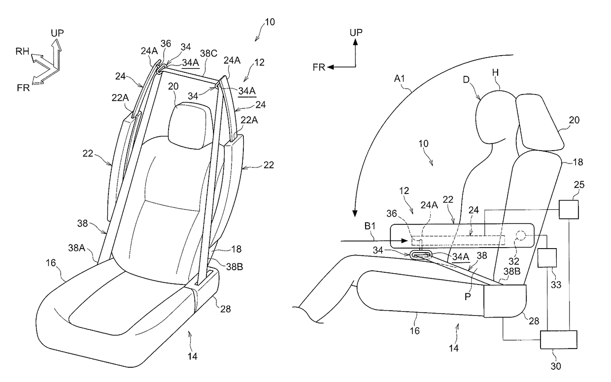
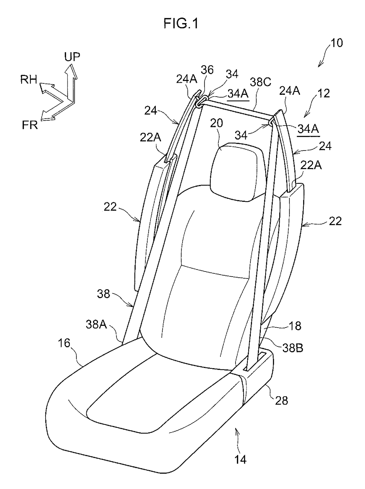
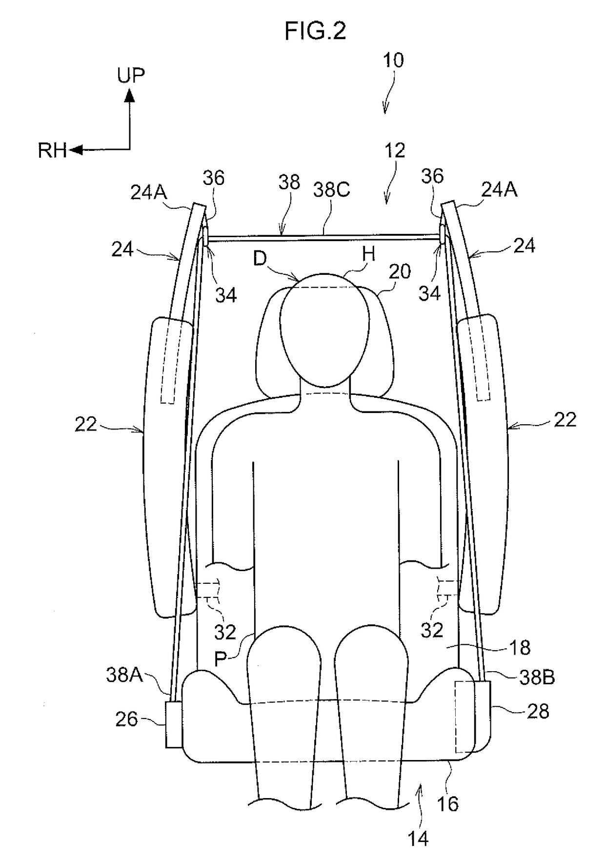
[0051]An occupant protection system 10 equipped with a vehicle seat belt device 12 pertaining to a first embodiment will now be described with reference to FIG. 1 to FIG. 8. It should be noted that arrow FR in the drawings indicates a seat forward direction of a vehicle seat 14 to which the vehicle seat belt device 12 has been applied, arrow UP indicates a seat upward direction, and arrow RH indicates a seat rightward direction.

[0052]As shown in FIG. 1 to FIG. 3, the vehicle seat 14 (hereinafter simply called “the seat 14”) to which the occupant protection system 10 pertaining to the present embodiment has been applied is configured to include a seat cushion 16 and a seat back 18. Furthermore, a head rest 20 is disposed on the upper end portion of the seat back 18.

[0053]It should be noted that the drawings show a state in which a crash test dummy, serving as a model of an occupant to be protected, is seated on the seat cushion 16 of the seat 14. The dummy is, for example, World Side...

second embodiment

[0103]Next, an occupant protection system 70 equipped with a vehicle seat belt device 71 pertaining to a second embodiment will be described with reference to FIG. 11 to FIG. 16. In the present embodiment, the occupant protection system 70 has a configuration that automatically engages a so-called three-point seat belt. It should be noted that, regarding configurations that are the same as those in the first embodiment, the same reference signs are assigned thereto and description thereof will be appropriately omitted. Furthermore, an airbag device configuring the occupant protection system 70 of the present embodiment is the same as the airbag device 13 of the first embodiment shown in FIG. 8, so illustration and description thereof will be omitted, and here only the vehicle seat belt device 71 will be described.

[0104]As shown in FIG. 11, in the vehicle seat belt device 71 configuring the occupant protection system 70 of the present embodiment, a first belt anchor 72 is disposed on...


PUM


Abstract

An occupant protection system includes: arm rests that are disposed on first and second width direction sides of a seat back and are rotatable between a substantially vertical storage position and a substantially horizontal use position; slide members that are slidable along the arm rests and have belt guides; a retractor that takes up webbing of a belt; and an electronic control unit that, (i) in a state before an occupant is seated in a vehicle seat, causes the arm rests to be held in the storage position and causes the slide members to slide in the seat upward direction above the head of the occupant, and that, (ii) when the occupant is seated, causes the arm rests to rotate to the use position, causes the slide members to slide toward base sides of the arm rests, and causes the webbing to be taken up by the retractor.

Description

CROSS-REFERENCE TO RELATED APPLICATION[0001]This application claims priority under 35 USC 119 from Japanese Patent Application No. 2015-166000 filed Aug. 25, 2015, the entire disclosure of which is incorporated by reference herein.BACKGROUND[0002]Technical Field[0003]The disclosure relates to a vehicle seat belt device and an occupant protection system.[0004]Related Art[0005]As a seat belt device that can automatically engage and disengage a seat belt, Japanese Patent Application Laid-open (JP-A) No. 2009-279985 discloses a structure where motors disposed on a vehicle seat and take-up members attached to a roof are coupled to each other in the seat up and down direction by wires. Furthermore, the structure is disposed with joints that are movable in the seat up and down direction along the wires, and a belt (webbing) whose end portions are anchored to the roof and that bridges the joints. Additionally, the belt is placed on the roof side together with the joints in a state before en...

Claims


Application Information

Patent Timeline
Patent Type & Authority Patents(United States)
IPC IPC(8): B60R22/04B60R22/34B60R22/26B60R22/195B60R21/207B60N2/46B60R22/00B60R22/48B60R21/00B60R22/18B60N2/75
CPCB60R22/04B60N2/468B60R21/207B60R22/00B60R22/195B60R22/26B60R22/34B60R22/48B60N2/4606B60R2022/4808B60R2021/0032B60R2021/0048B60R2021/2074B60R2022/1818B60R2022/1957B60R22/20B60N2/753B60N2/79
Inventor KONDO, TORUOHNO, MITSUYOSHI
Owner TOYOTA JIDOSHA KK
Learn More